
Mine machine damping base

A technology for mechanical shock absorption and mining, applied in the field of shock absorption machinery, can solve the problems of affecting the performance, poor shock absorption effect, and inability to satisfy users.

Inactive Publication Date: 2017-11-17
山东恒德智能装备科技有限公司
View PDF1 Cites 10 Cited by
  • Summary
  • Abstract
  • Description
  • Claims
  • Application Information

AI Technical Summary

Problems solved by technology

At present, the mining machinery on the market will generate great vibration during use, which will easily cause equipment damage and affect normal production. However, the existing mining machinery shock absorption measures are not perfect, and all of them are set up on the mining machinery. The structure absorbs its shock, but the shock-absorbing structure is relatively simple, and the shock-absorbing effect is not ideal enough to satisfy users
[0003] The Chinese patent with the application number 201420780925.8 discloses a shock-absorbing base, which is characterized in that it includes a bottom support seat, a damping rubber layer, a spring shock-absorbing layer, a top support seat, a U-shaped reinforcement and several bolts arranged in sequence from bottom to top. The support base and the top support base are provided with several corresponding threaded holes, and the two arms of the U-shaped reinforcement are provided with through holes for bolts to pass through. The bottom support base, damping rubber layer, spring shock-absorbing layer and The top supporting base is firmly installed into one body. Although the above-mentioned shock-absorbing base is convenient to manufacture and use to a certain extent, the shock-absorbing effect is not good, which affects the performance

Method used


Image

  • Mine machine damping base
  • Mine machine damping base

Examples


Embodiment Construction

[0021] In order to make the purpose, technical solutions and advantages of the embodiments of the present invention clearer, the technical solutions in the embodiments of the present invention will be clearly and completely described below in conjunction with the drawings in the embodiments of the present invention. Obviously, the described embodiments It is a part of embodiments of the present invention, but not all embodiments. Based on the embodiments of the present invention, all other embodiments obtained by persons of ordinary skill in the art without creative efforts fall within the protection scope of the present invention.

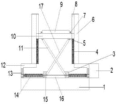
[0022] A mining machinery shock absorbing base, comprising a base 1, a support base 12 is provided on the left and right sides of the top of the base 1, a column 6 is arranged on the support base 12, a chute 8 is fixedly connected to the column 6, and the left and right ends of the sliding plate 10 respectively arranged in the chute 8 on the left ...


PUM


Abstract

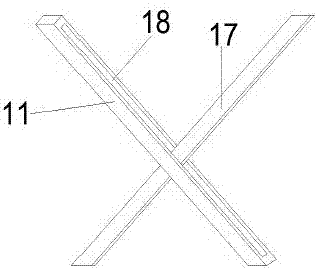
The invention provides a mining machinery shock absorbing base, which relates to the field of shock absorbing machinery, including a base, a support seat is provided on the left and right sides of the top of the base, a column is provided on the support seat, a chute is fixedly connected with the column, and the left and right sides of the sliding plate The ends are respectively set in the chute on the left and right sides. There is a No. 1 spring in the chute. The upper end of the No. 1 spring is fixedly connected with the bottom of the sliding plate, and the lower end of the No. 1 spring is fixedly connected with the bottom of the chute. There is an "X" under the sliding plate. There are rollers at the lower end of the "X"-shaped bracket, slide rails are set on the top of the base, and the rollers are set in the slide rails. There are baffles on the left and right sides of the "X"-shaped bracket, and one end of the No. 2 spring is fixed to the baffle. connection, the other end of the No. 2 spring is fixedly connected with the support seat, and the right side of the support seat on the right side is provided with a fan. The invention has the advantages of simple structure, good stability, good shock absorption effect, and can effectively prolong the service life of mining machinery. advantage.

Description

technical field [0001] The invention relates to the field of shock-absorbing machinery, in particular to a mining machinery shock-absorbing base. Background technique [0002] Mining machinery is directly used for mineral mining and enrichment and other operations. Including mining machinery and beneficiation machinery. The working principle and structure of prospecting machinery are mostly the same or similar to the mining machinery used to mine similar minerals. In a broad sense, prospecting machinery also belongs to mining machinery. In addition, a large number of cranes, conveyors, fans and drainage machinery are also used in mine operations. At present, the mining machinery on the market will generate great vibration during use, which will easily cause equipment damage and affect normal production. However, the existing mining machinery shock absorption measures are not perfect, and all of them are set up on the mining machinery. The structure dampens it, but the dam...

Claims


Application Information

Patent Timeline
IPC IPC(8): F16M5/00F16F15/04
CPCF16M5/00F16F15/04
Inventor 张华彬张鹏张倩倩
Owner 山东恒德智能装备科技有限公司
Learn More