Novel water cup device

A water cup, a new technology, applied in the direction of the coupling device, the parts of the connecting device, drinking utensils, etc., can solve the problems of unstable locking mode, user inconvenience, power supply interruption, etc., to improve the safety of power supply, prevent electric shock accidents, The effect of improving the stability of the plug

Inactive Publication Date: 2017-11-03
何杨波
View PDF6 Cites 4 Cited by
  • Summary
  • Abstract
  • Description
  • Claims
  • Application Information

AI Technical Summary

Problems solved by technology

The electric water cup needs to be plugged into the socket for power supply before it can be used. Since the socket is directly charged and the conductive sheet is set relatively outside, it may cause electric shock accidents under human careless touch, and there is a large safety hazard. At the same time, The traditional electric water cup uses the friction between the plug and the socket to realize the locked state when the power supply is plugged in. However, this locking method is extremely unstable, and it is very easy to be affected by dragging and pulling the power supply line after plugging, resulting in plugging. If the connection is loose, the power supply is interrupted, which has great disadvantages and brings great inconvenience to users.

Method used


Image

  • Novel water cup device
  • Novel water cup device
  • Novel water cup device

Examples


Embodiment Construction

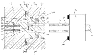
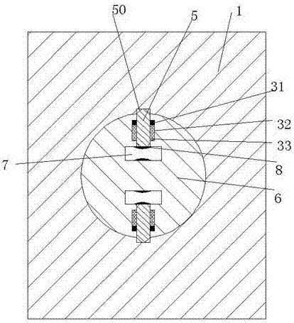
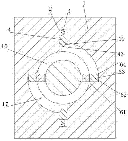
[0027] Combine below Figure 1-7 The present invention will be described in detail.

[0028] refer to Figure 1-7 , a new water cup device according to an embodiment of the present invention, comprising a water cup 100, a plug 21 electrically connected to the water cup through a power cord 103, and a socket 1 mated with the plug, and a handle 102 is provided on the right end of the water cup 100, The socket 1 is provided with a rotating hole with the port facing right, and a rotating member 6 is rotatably installed in the rotating hole, and the rotating member 6 is provided with a left and right connecting slot 7 in the upper and lower sides. 7 is fixedly installed with a conductive sheet 8, and a gasket 11 is fixedly installed in the middle of the left end surface of the rotating member 6, and the left end surface of the gasket 11 is provided with a slot hole, and the socket 1 is located at the left end of the rotation hole. An annular groove 16, an intermediate groove 15 i...


PUM


Abstract

The invention provides a novel water cup device. The device includes a water cup, a plug and a socket, wherein the plug is electrically connected with the water cup through a power line, and the socket is connected with the plug in a cooperation mode; the end face of the right side of the water cup is provided with a handle, the socket is internally provided with a rotating hole with a port facing to the right, a rotating component is rotatably installed in the rotating hole, inserted grooves symmetrical up and down are arranged in the rotating component and communicated left and right, conductive sheets are fixedly installed in the inserted grooves, the middle of the left end face of the rotating component is fixedly provided with a gasket, the left end face of the gasket is provided with a groove hole, the socket is located at the left end of the rotating hole and is provided with a ring groove, the middle of the left end of the ring groove is provided with a middle groove, a sliding part which can slide left and right is installed in the middle groove, the middle of the right end face of the sliding part is fixedly provided with a pin rod, the end wall of the ring groove is internally provided with half-ring grooves located on the back upper portion of the sliding part and the front lower portion of the sliding part respectively, the end wall of the ring groove is internally provided with contraction grooves which are symmetrical up and down and can extend up and down, the contraction grooves are communicated with the half-ring grooves, and electricity transmission blocks are installed in the contraction grooves in a sliding mode.

Description

technical field [0001] The invention relates to the technical field of water cups, in particular to a novel water cup device. Background technique [0002] Water cups are living utensils that are often used in daily life. With the continuous development of science and technology, some water cups that use electricity to boil water are gradually integrated into people's lives and become an important part of daily utensils. The electric water cup needs to be plugged into the socket for power supply before it can be used. Since the socket is directly charged and the conductive sheet is set relatively outside, it may cause electric shock accidents under human careless touch, and there is a large safety hazard. At the same time, The traditional electric water cup uses the friction between the plug and the socket to realize the locked state when the power supply is plugged in. However, this locking method is extremely unstable, and it is very easy to be affected by dragging and pul...

Claims


Application Information

Patent Timeline
IPC IPC(8): A47G19/22A47J27/21H01R13/71H01R13/639
CPCA47G19/2205A47J27/21008H01R13/639H01R13/71
Inventor 何杨波
Owner 何杨波
Why Eureka
Try Eureka