Production line for producing fluorescent materials through two-step method

A fluorescent material and production line technology, applied in the field of fluorescent material processing equipment, can solve the problems of residue, waste of raw materials, easy sticking, etc., and achieve the effects of low processing cost, high processing efficiency, and avoidance of raw material loss

Inactive Publication Date: 2017-10-24
扬州辰鑫新材料科技有限公司
View PDF6 Cites 0 Cited by
  • Summary
  • Abstract
  • Description
  • Claims
  • Application Information

AI Technical Summary

Problems solved by technology

However, people have found in the actual use process that although the finished fluorescent material has certain fluidity at high temperature, it will also have a relatively high viscosity due to the loss of water, so it is very easy to stick and remain in the reactor. middle
In this way, the reactor needs to be manually chemically treated after each discharge (adding chemicals to clean the reactor), resulting in a substantial increase in the processing cycle and processing cost of the finished fluorescent material, and accompanied by A large amount of waste of raw materials further increases the processing cost of finished fluorescent materials
[0003] In addition, since the finished fluorescent material will carry a higher temperature after being poured out, the traditional method of manual deployment and transfer will have extremely high labor intensity and potential safety hazards

Method used


Image

  • Production line for producing fluorescent materials through two-step method
  • Production line for producing fluorescent materials through two-step method
  • Production line for producing fluorescent materials through two-step method

Examples


Embodiment Construction

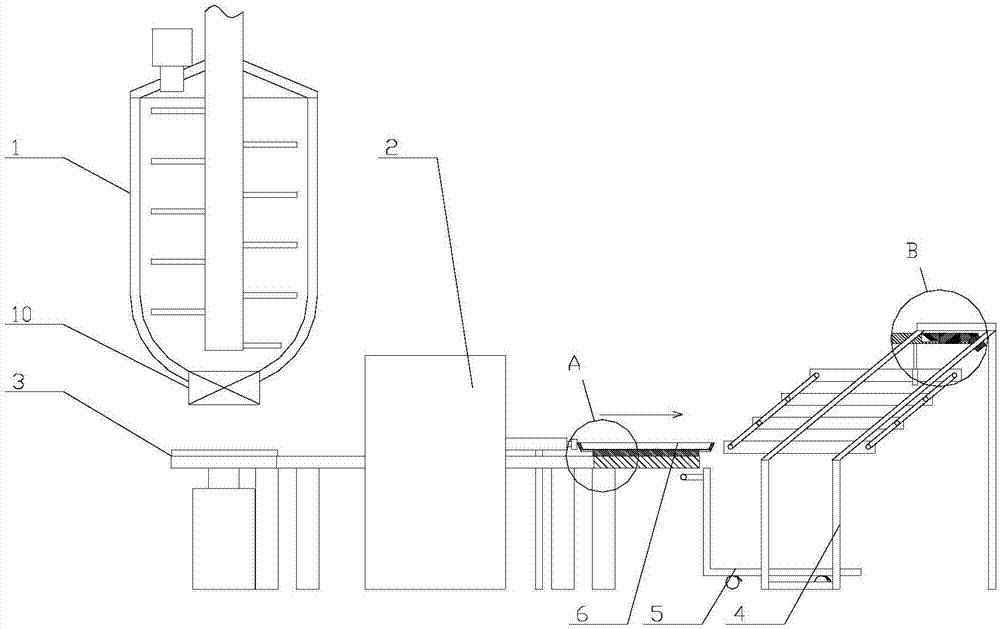
[0028] The present invention as Figure 1-9 As shown, it comprises a reactor 1, a drying box 2, a transfer device 3, a distributing device 4, a trolley 5 and several trays 6, and the reactor 1 is arranged on one side of the drying box 2; the top of the reactor is provided with There is a feeding valve, and the bottom of the reaction kettle 1 is provided with a feeding valve 10, and the side of the drying box facing the reaction kettle is provided with a feeding port, and the side facing away from the reaction kettle is provided with a discharge port;

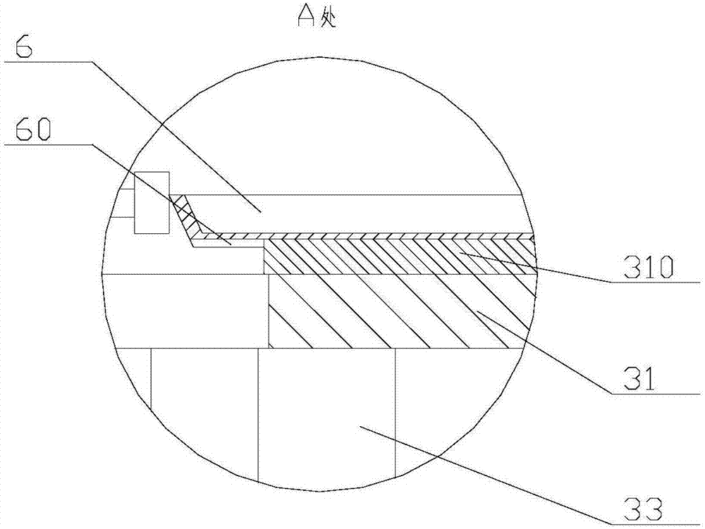
[0029] The transfer device 3 includes a transfer plate 31, a transfer drive device 32 and several support columns 33, the transfer plate 31 is in the shape of a ring, and is slidably connected to the tops of several support columns 33 fixedly connected on the ground, the transfer The driving device 32 is connected to the bottom surface of the transfer plate 31 and is used to drive the transfer plate 31 to rotate around its own a...


PUM


Abstract

A production line for producing fluorescent materials through a two-step method relates to the field of processing equipment for fluorescent materials and has fine-designed structure, high processing efficiency, low processing cost and high automation degree and is free of safety risk. The production line includes: a reaction kettle, a drying box, a transportation apparatus, a material distributing apparatus, a trolley, and a plurality of trays. The reaction kettle is arranged at one side of the drying box; the transportation apparatus includes a transportation plate, a transportation driving device and a plurality of support columns; the transportation plate is annular in shape and is slidingly connected to the top ends of the support columns; the transportation driving device is connected to the bottom surface of the transportation plate and is used for driving the transportation plate to rotate around the axis thereof; the transportation plate is horizontally arranged below the reaction kettle and penetrates through the drying box. A two-step method including reaction and then drying is used for preparing and temporarily storing a finish product of fluorescent material, so that a problem of loss of raw materials due to adhesion during processing is effectively avoided. Totally, the production line is high in processing efficiency and is low in processing cost.

Description

technical field [0001] The invention relates to the field of fluorescent material processing equipment. Background technique [0002] At present, the preparation process of fluorescent materials is usually to directly add all the powdery raw materials and water into the reactor for stirring and heating until the reaction is complete and the water is evaporated, and then the finished product is directly poured out of the reactor. However, people have found in the actual use process that although the finished fluorescent material has certain fluidity at high temperature, it will also have a relatively high viscosity due to the loss of water, so it is very easy to stick and remain in the reactor. middle. In this way, the reactor needs to be manually chemically treated after each discharge (adding chemicals to clean the reactor), resulting in a substantial increase in the processing cycle and processing cost of the finished fluorescent material, and accompanied by A large amou...

Claims


Application Information

Patent Timeline
Patent Type & Authority Applications(China)
IPC IPC(8): B01J19/18C09K11/00F26B9/06B65G47/74
CPCB01J19/18F26B9/06C09K11/00B65G47/74
Inventor 徐斌杨立新潘煜怡
Owner 扬州辰鑫新材料科技有限公司
Why Eureka
Try Eureka