


Quick Research
Generate reliable direction feasibility study reports for your R&D in just a few steps.

Technical Q&A
Discover and master advanced knowledge NOW. Basics, ideas, possibilities, all at once.

Find Solutions
As an expert in R&D theories, this can generate solutions to your technical problems instantly.

Evaluate Feasibility
Analyze your overall solution with one click, know your potential R&D risks in advance.

Monitor Landscape
Get weekly tech updates, stay abreast of the latest tech innovations and key insights.
A relay moving part detection circuit and a relay having the circuit
A technology of moving parts and detection circuits, which is applied in the direction of circuit breaker testing, relays, electromagnetic relays, etc., can solve the problems of not having self-detection on-off state and fault state, unfavorable control system maintenance, delay in circuit fault detection, etc., to achieve Effect of Improving the Efficiency of Circuit Fault Detection
- Summary
- Abstract
- Description
- Claims
- Application Information
AI Technical Summary
Problems solved by technology
Method used
Image

Examples
Embodiment 1
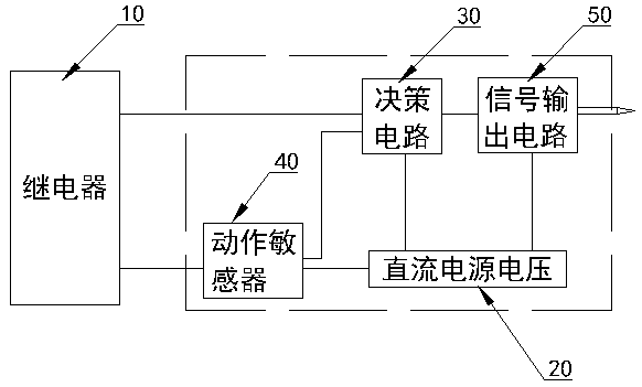
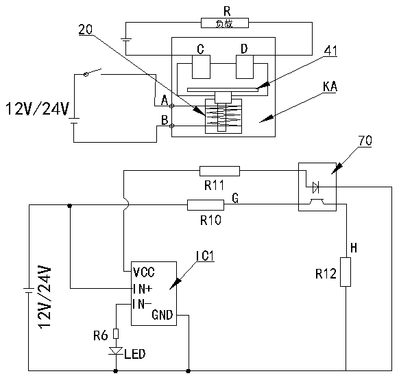
[0019] figure 1 , image 3 In the shown embodiment, a relay moving part detection circuit includes a relay 10 and a DC power supply voltage 20, and also includes a decision circuit 30, a motion sensor 40 and a signal output circuit 50, and the decision circuit 30 includes a moving part detection device , the moving part detection device comprises an infrared sensor 70 and a voltage comparator IC1, and the motion sensor 40 is a relay moving part 41; the output terminal of the decision circuit 30 is electrically connected with the signal output circuit 50, and the front stage of the decision circuit 30 is connected with the motion sensor 40 respectively. Electrically connected with the relay 10, the infrared sensor 70 detects the position change of the relay moving part 41, and the decision circuit 30 and the motion sensor 40 are electrically connected with the DC power supply voltage 20 respectively; the decision circuit 30 detects the relay moving part according to the infrare...
Embodiment 2
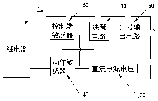
[0023] figure 2 , Figure 4In the shown embodiment, the control terminal sensor 40 is electrically connected to the front stage of the decision circuit 30, and the control terminal sensor 40 adopts a photocoupler 80. The decision circuit also includes a control terminal sensor detection device, and the control terminal sensor detection device The device includes a relay coil AB, a second voltage comparator IC2 and a third voltage comparator IC3; the control terminal sensor 40 detection device detects whether the relay coil AB is energized, and then judges whether the relay 10 is qualified through the signal output indication of the signal output circuit 50. The input terminal of optocoupler 80 is connected in series with the two ends of relay coil AB through the first resistor R1, the second resistor R2 to form the input loop of optocoupler 80; the level output terminal F of optocoupler 80 is connected with the third The comparison input terminal IN+pin IN+1 of the voltage c...
Embodiment 3
[0025] A relay, including a relay packaging case, and also includes the relay moving part detection circuit described in embodiment 1 or embodiment 2, the relay packaging case, relay coil, relay contacts, relay moving parts, and decision-making circuit are jointly arranged and connected into an integrated form finished relays.
PUM
 Abstract
Description
Claims
Application Information
 - R&D Engineer
- R&D Manager
- IP Professional
- Industry Leading Data Capabilities
- Powerful AI technology
- Patent DNA Extraction
Browse by: Latest US Patents, China's latest patents, Technical Efficacy Thesaurus, Application Domain, Technology Topic, Popular Technical Reports.
© 2024 PatSnap. All rights reserved.Legal|Privacy policy|Modern Slavery Act Transparency Statement|Sitemap|About US| Contact US: help@patsnap.com