Electrical plugging assembly

A technology of components and sockets, applied in electrical components, circuits, coupling devices, etc., can solve problems such as death, power failure, safety hazards, etc., and achieve the effect of convenient use, simple device structure, and reduction of electric shock accidents.

Active Publication Date: 2017-10-17
JIASHAN HUIJIALE DECORATION MATERIALS CO LTD
View PDF6 Cites 2 Cited by
  • Summary
  • Abstract
  • Description
  • Claims
  • Application Information

AI Technical Summary

Problems solved by technology

[0002] Electrical equipment generally needs to be powered on to operate, and electrical equipment is powered by the use of plug connectors and socket sockets. Traditional plugs and socket sockets use the gap between the two. Friction achieves the locking of the state when inserted, but this locking method is extremely unstable. When the plug connector is accidentally touched or kicked, it is easy to separate or loosen the plug connector and the socket socket. Therefore, power failure is prone to occur. , and in the traditional socket, the elastic conductive sheet is almost leaking, and can be touched by a metal sheet or a rod. Since the elastic conductive sheet is generally directly connected to the mains, once the metal sheet or rod It can be charged when it touches the elastic conductive sheet. If some people (such as young children) who lack safety awareness insert iron rods, keys and the like into the socket and touch the elastic conductive sheet, they will get an electric shock. Safety accidents can cause human death in severe cases. Therefore, there are great safety hazards in traditional power supply sockets

Method used


Image

  • Electrical plugging assembly
  • Electrical plugging assembly
  • Electrical plugging assembly

Examples


Embodiment Construction

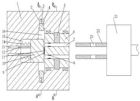
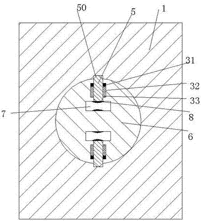
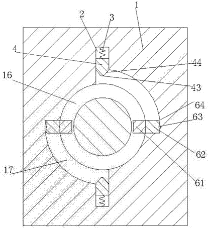
[0026] Combine below Figure 1-7 The present invention will be described in detail.

[0027] refer to Figure 1-7 , according to an embodiment of the present invention, an electric plug-in assembly includes a socket socket fixedly installed in the wall and a plug connector 21 connected to the electrical equipment, the socket socket 1 is provided with a right-opening Rotation hole, the rotation member 6 is rotatably installed in the rotation hole, and the insertion groove 7 connected to the left and right is symmetrically arranged in the rotation member 6 up and down, and the elastic conductive sheet 8 is fixedly installed in the insertion groove 7, A rubber sheet 11 is fixedly installed at the center of the left end surface of the rotating member 6, and the left end surface of the rubber sheet 11 is provided with a concave hole, and the socket 1 is provided with a circular groove 16 at the left end of the rotating hole. The center of the left end of the circular groove 16 is...


PUM


Abstract

The invention relates to an electrical plugging assembly comprising a plugging base fixedly installed in a wall and a plugging head connected with an electrical device. A rotating hole with an opening to the right is formed in the plugging base; a rotating element is installed in the rotating hole is a rotatable manner; plugging slots that are arranged in a up-down symmetric manner and are communicated in a left-right manner are formed in the rotating element; and elastic conductive pieces are fixedly installed in the plugging slots. A rubber sheet is fixedly installed in the center of the left end surface of the rotating element; and a recession hole is formed in the left end surface of the rubber sheet. A circular groove is formed in the plugging base at the left end of the rotating hole; a central groove is formed in the center of the left end of the circular groove; a sliding element is installed in the central groove in a left-right sliding manner; and a pin is fixedly installed in the center of the right end surface of the sliding element. Arc rotating slots are formed above the rear of the sliding element and below the front of the sliding element in the end wall of the circular groove; extension slots extending up and down are formed in the end wall of the circular groove in an up-down symmetric manner; the extension slots and the arc rotating slots are communicated; and power supply blocks are installed in the extension slots in a sliding manner.

Description

technical field [0001] The invention relates to the field of power supply for electrical equipment, in particular to an electrical insertion assembly. Background technique [0002] Electrical equipment generally needs to be powered on to operate, and electrical equipment is powered by the use of plug connectors and socket sockets. Traditional plugs and socket sockets use the gap between the two. Friction achieves the locking of the state when inserted, but this locking method is extremely unstable. When the plug connector is accidentally touched or kicked, it is easy to separate or loosen the plug connector and the socket socket. Therefore, power failure is prone to occur. , and in the traditional socket, the elastic conductive sheet is almost leaking, and can be touched by a metal sheet or a rod. Since the elastic conductive sheet is generally directly connected to the mains, once the metal sheet or rod It can be charged when it touches the elastic conductive sheet. If som...

Claims


Application Information

Patent Timeline
IPC IPC(8): H01R13/71H01R13/627H01R13/502
CPCH01R13/502H01R13/6278H01R13/71
Inventor 冯斌斌
Owner JIASHAN HUIJIALE DECORATION MATERIALS CO LTD
Why Eureka
Try Eureka