Multifunctional centralized control mechanism

A control mechanism and centralized technology, applied in the direction of control components, mechanical control devices, control/adjustment systems, etc., can solve problems such as heavy weight, difficult braking, hidden safety hazards, etc., to achieve simple and centralized operation, intuitive and convenient maintenance, low cost effect

Active Publication Date: 2017-10-13
山东森亚信息科技有限公司
View PDF8 Cites 2 Cited by
  • Summary
  • Abstract
  • Description
  • Claims
  • Application Information

AI Technical Summary

Problems solved by technology

However, equipment such as electric carts and small pumps have relatively large self-weight and loaded materials, and their inertia is also relatively large.
In the process of driving, in an emergency situation, the driver will instinctively apply force to the opposite direction of the vehicle. At this time, it is difficult for unskilled drivers to press the steering arm or the brake steering lever to perform the brake operation. Especially when reversing (that is, when driving in the direction of the driver), the push-down brake operation mode, the braking force direction is the same as the driving direction, and the braking is difficult and insensitive. In actual construction, the driver usually needs to rely on binding and setting up obstacles Only external braking measures such as objects can enter the construction material platform and other similar positions, which will bring troubles and potential safety hazards to the actual construction.

Method used


Image

  • Multifunctional centralized control mechanism
  • Multifunctional centralized control mechanism
  • Multifunctional centralized control mechanism

Examples


Embodiment Construction

[0016] The following will clearly and completely describe the technical solutions in the embodiments of the present invention with reference to the accompanying drawings in the embodiments of the present invention. Obviously, the described embodiments are only some, not all, embodiments of the present invention.

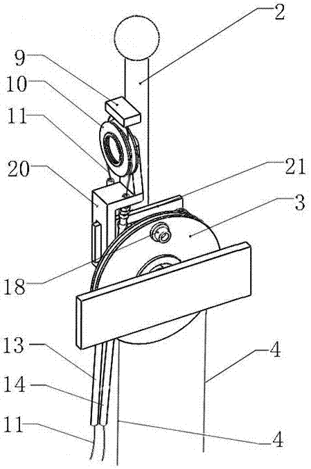
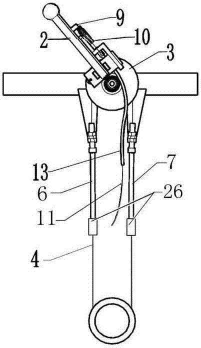
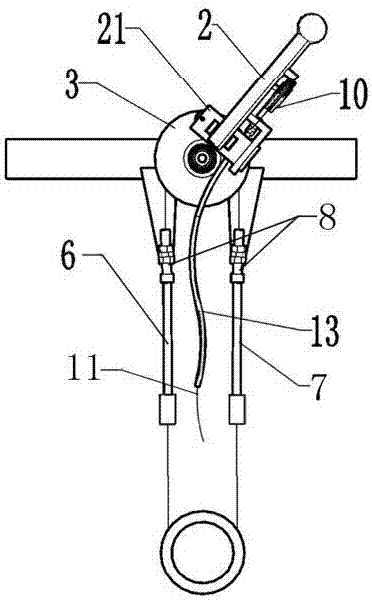
[0017] refer to Figure 1-5 , a multifunctional centralized control mechanism, including a handle bar 2, a main sheave 3, a rope arm 9, a secondary sheave 10, a rope and a reset device, the rope includes a rope c4 and a rope a11, and the rope The rope is preferably a steel wire rope. The handle hinge seat 15 at the lower end of the handle bar 2 is hinged with the sheave hinge seat 19 on the end face of the main sheave 3. One side of the handle bar 2 is also fixed with a pull rope arm 9, a pull rope arm 9 and a stay rope a11 The upper end of the pulley is fixed, the stay rope a11 is bypassed from the rope groove of the auxiliary sheave 10, and the lower end of the sta...


PUM


Abstract

The invention discloses a multifunctional centralized control mechanism. The multifunctional centralized control mechanism comprises a handle lever, a main rope wheel, a stay cord arm, an auxiliary rope wheel, a stay cord and a reset device, the stay cord comprises a stay cord body c and a stay cord body a, a handle hinged support at the lower end of the handle level is hinged to a rope wheel hinged support on the end face of the main rope wheel, the stay cord arm is fixed to one side of the handle level, the stay cord arm is fixed to the upper end of the stay cord body a, the stay cord body a winds around a rope groove of the auxiliary rope wheel, and the lower end of the stay cord body a is connected with a brake actuating component; the auxiliary rope wheel is installed on a rope wheel support, the rope wheel support is fixed to the end face of the main rope wheel, the stay cord body c winds around a rope groove of the main rope wheel, the say cord body c is fixed to the main rope wheel through a stay cord fixing clip, the lower end is connected with a steering actuating component, the reset device is arranged on the end face of the main rope wheel, multiple functions are integrated in a handle, operation is conducted in an easy, concentrated, rapid and convenient mode, the size is small, few conduction transmission links exist, few faults exist, the cost is low, maintenance is conducted in a visual and convenient mode, the operation driving instinct is visual, and particularly, safety is more obvious on a material platform.

Description

technical field [0001] The invention belongs to an operation control device, in particular to a multifunctional centralized control mechanism. Background technique [0002] At present, limited by some construction environments, machines such as electric carts and small pumps need to be driven and controlled but have no driving position. Operators must control while walking, and need to control their direction, speed, forward and reverse. , and can brake in time, that is, on the premise of a sufficiently small volume, it can meet the necessary functional requirements for the above operations. An electric cart proposed in Patent No. 201520842271.1 and an electric cart proposed in Patent No. 201620874049.4 both require the driver to drive while walking, and control the speed and direction of the electric cart through the control arm or the brake steering lever. Press down on the directional control arm or brake steering lever to apply the brakes. However, equipment such as el...

Claims


Application Information

Patent Timeline
Patent Type & Authority Applications(China)
IPC IPC(8): G05G1/04
CPCG05G1/04
Inventor 王德宇
Owner 山东森亚信息科技有限公司
Why Eureka
Try Eureka