Bypass device for quickly mounting capillary pipe on farm irrigation branch pipe

A bypass and branch pipe technology, applied in branch pipelines, pipes/pipe joints/pipes, pipes, etc., can solve the problems of high operator requirements, large workload, low work efficiency, etc., and meet professional skills requirements. Low, fast installation process, simple structure effect

Active Publication Date: 2017-10-13
河北省农业机械化研究所有限公司 +1
View PDF6 Cites 1 Cited by
  • Summary
  • Abstract
  • Description
  • Claims
  • Application Information

AI Technical Summary

Problems solved by technology

[0002] The field sprinkler irrigation system usually includes branch pipes and capillary pipes connected to them. The branch pipes are provided with connection holes at equal intervals, and then the bypass is delivered to the connection hole position from one end of the branch pipe in sequence, and then the bypass device is sent from the connection hole position. Pull out and screw on the bypass screw, and finally realize the fixed connection of the bypass device to the connecting hole of the branch pipe. Such an operation method results in low work efficiency due to cumbersome operations. It mainly depends on the proficiency of the operator to improve work efficiency. The personnel requirements are relatively high, and the labor of installing the capillary pipe in the large-area irrigation system is relatively large, so the existing bypass device needs to be improved

Method used


Image

  • Bypass device for quickly mounting capillary pipe on farm irrigation branch pipe
  • Bypass device for quickly mounting capillary pipe on farm irrigation branch pipe
  • Bypass device for quickly mounting capillary pipe on farm irrigation branch pipe

Examples


Embodiment Construction

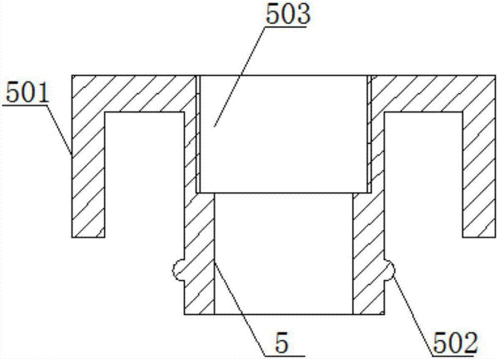
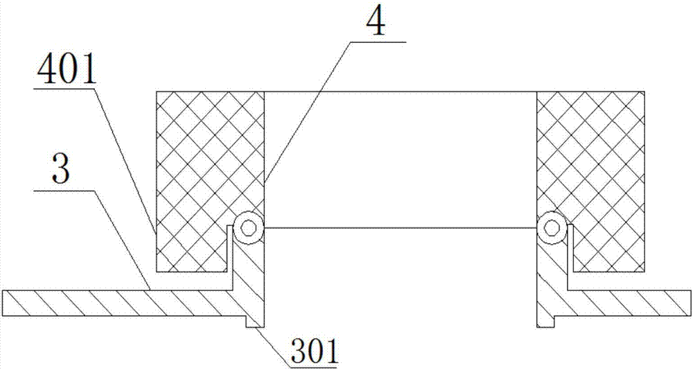
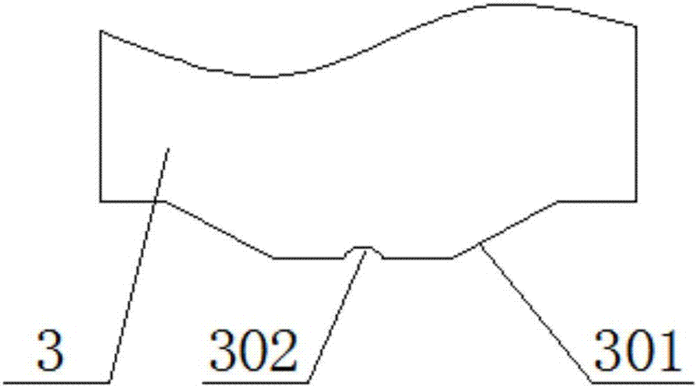
[0018] The invention relates to a bypass device for quickly installing capillary pipes on field irrigation branch pipes. The bypass device includes locking buckles and snap-fit ​​buckles, and the locking buckles include L-shaped clamping plates on both sides of the lower end. 3, the support tube 4, the upper part of the support tube 4 is provided with a limit platform 401, and the limit platform 401 forms the limit position of the support tube 4 in the vertical direction by means of the contact between its lower end surface and the branch pipe 1, and the snap-fit ​​buckle includes plugging into the support tube 4. The snap-in tube 5 in the tube 4, the upper end of the inner hole of the snap-in tube 5 is provided with an internal thread hole 503 matching the external thread of the end of the capillary tube 2, and the outside of the snap-in tube 5 is provided with a top-tightening tube 501 covering the locking buckle , the L-shaped clamping plate 3 and the top clamping pipe 501 f...


PUM


Abstract

The invention provides a bypass device for quickly mounting a capillary pipe on a farm irrigation branch pipe, and belongs to the technical field of pipe connection. The bypass device comprises a locking buckle and a clamping buckle. The locking buckle comprises a supporting pipe. L-shaped clamping pipes are separately arranged on two sides of the lower end of the supporting pipe. A spacing table is arranged at the upper part of the supporting pipe. Spacing of the supporting pipe in the vertical direction is realized by the spacing table by means of contact between the lower end surface of the spacing table and the supporting pipe. The clamping buckle comprises a clamping pipe inserted in the supporting pipe. An internal threaded hole matched with an external threaded hole in the end part of the capillary pipe is formed in the upper end of an inner hole of the clamping pipe. A propping pipe coating the locking buckle is arranged at the outer part of the clamping pipe. The L-shaped clamping plates and the propping pipe form a clamping unit for the pipe wall of the branch pipe by means of the spacing matching between the clamping pipe and the supporting pipe. Anti-withdrawing mechanisms are arranged between the clamping pipe and the L-shaped clamping pipes. When the bypass device is used, at first, the locking buckle is placed at the connection part of the branch pipe, then the raised part of the clamping buckle is inserted in the locking buckle along the sliding chute, and after rotation, quick connection between the branch pipe and the capillary pipe is completed, and the connection efficiency is remarkably improved.

Description

technical field [0001] The invention belongs to the technical field of pipeline connection, and relates to the connection of field irrigation pipelines, in particular to a bypass device for quickly installing capillary pipes on field irrigation branch pipes. Background technique [0002] The field sprinkler irrigation system usually includes branch pipes and capillary pipes connected to them. The branch pipes are provided with connection holes at equal intervals, and then the bypass is delivered to the connection hole position from one end of the branch pipe in sequence, and then the bypass device is sent from the connection hole position. Pull out and screw on the bypass screw, and finally realize the fixed connection of the bypass device to the connecting hole of the branch pipe. Such an operation method results in low work efficiency due to cumbersome operations. It mainly depends on the proficiency of the operator to improve work efficiency. The requirement for personnel...

Claims


Application Information

Patent Timeline
Patent Type & Authority Applications(China)
IPC IPC(8): F16L41/08
CPCF16L41/08Y02A40/22
Inventor 高清海贾建明刘胜尧袁兴茂范凤翠陈林石玉芳陈敬者马书强
Owner 河北省农业机械化研究所有限公司
Why Eureka
Try Eureka