
Movable cutting machine

A cutting machine and mobile technology, which is applied to shearing devices, accessories of shearing machines, shearing machine equipment, etc., can solve the problems of poor plate fixing effect, poor use effect and high risk, and increase the fixing effect and use. Great effect, low risk effect

Inactive Publication Date: 2017-10-13
张志通
View PDF9 Cites 3 Cited by
  • Summary
  • Abstract
  • Description
  • Claims
  • Application Information

AI Technical Summary

Problems solved by technology

[0002] The cutting machine is a tool that drives the blade through the transmission mechanism for cutting operations. It has the characteristics of safety, reliability, reasonable structure, and high work efficiency. It is suitable for cutting operations on materials such as stone and rigid materials. The cutting machine is manually adjusted during cutting. Placement position, such as the existing cutting machine, includes a housing, a blade cover connected to the housing, a handle, a motor is arranged in the housing, a blade is connected to the motor, the blade is located in the blade cover, and a lighting lamp is provided on the lower side of the housing. Although the cutting machine is designed with lights to facilitate night use, in actual use, it is not convenient for workers to adjust the cutting position and the next cut, and the fixing effect on the plate is poor, resulting in the plate being easily splashed after cutting , higher risk, less effective

Method used


Image

  • Movable cutting machine
  • Movable cutting machine
  • Movable cutting machine

Examples


Embodiment Construction

[0016] The following will clearly and completely describe the technical solutions in the embodiments of the present invention with reference to the accompanying drawings in the embodiments of the present invention. Obviously, the described embodiments are only some, not all, embodiments of the present invention. Based on the embodiments of the present invention, all other embodiments obtained by persons of ordinary skill in the art without making creative efforts belong to the protection scope of the present invention.

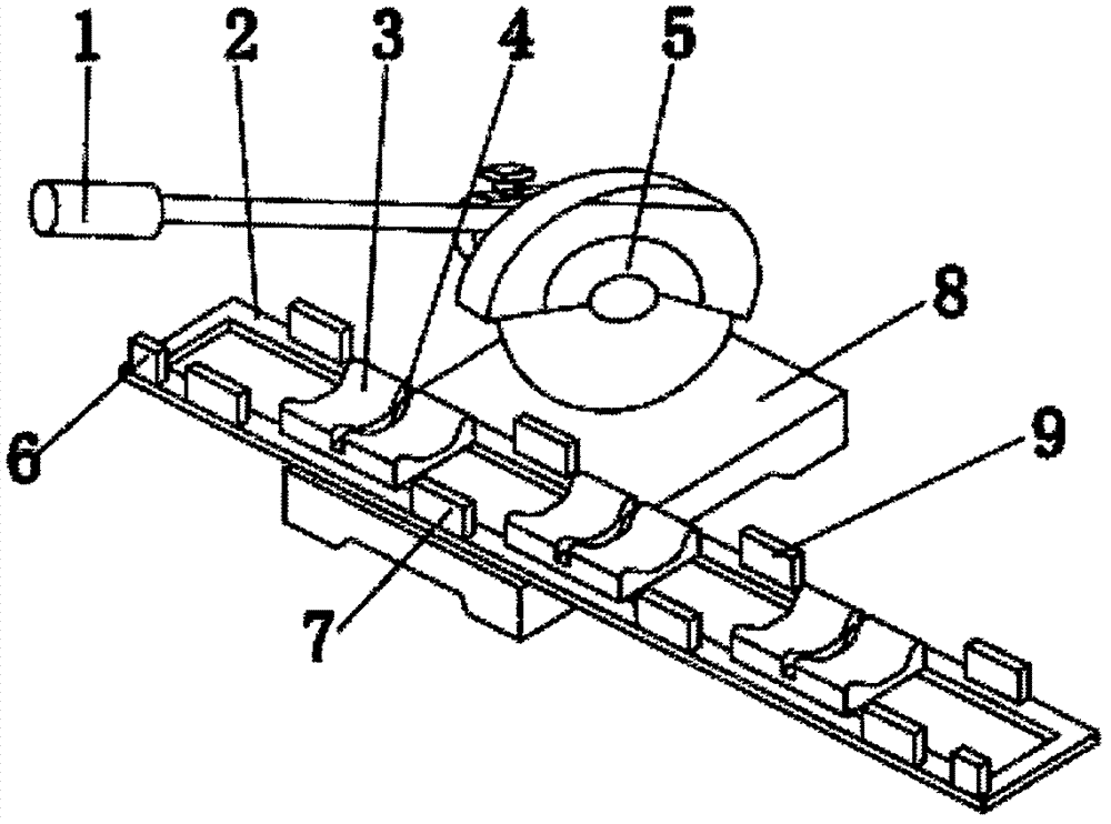
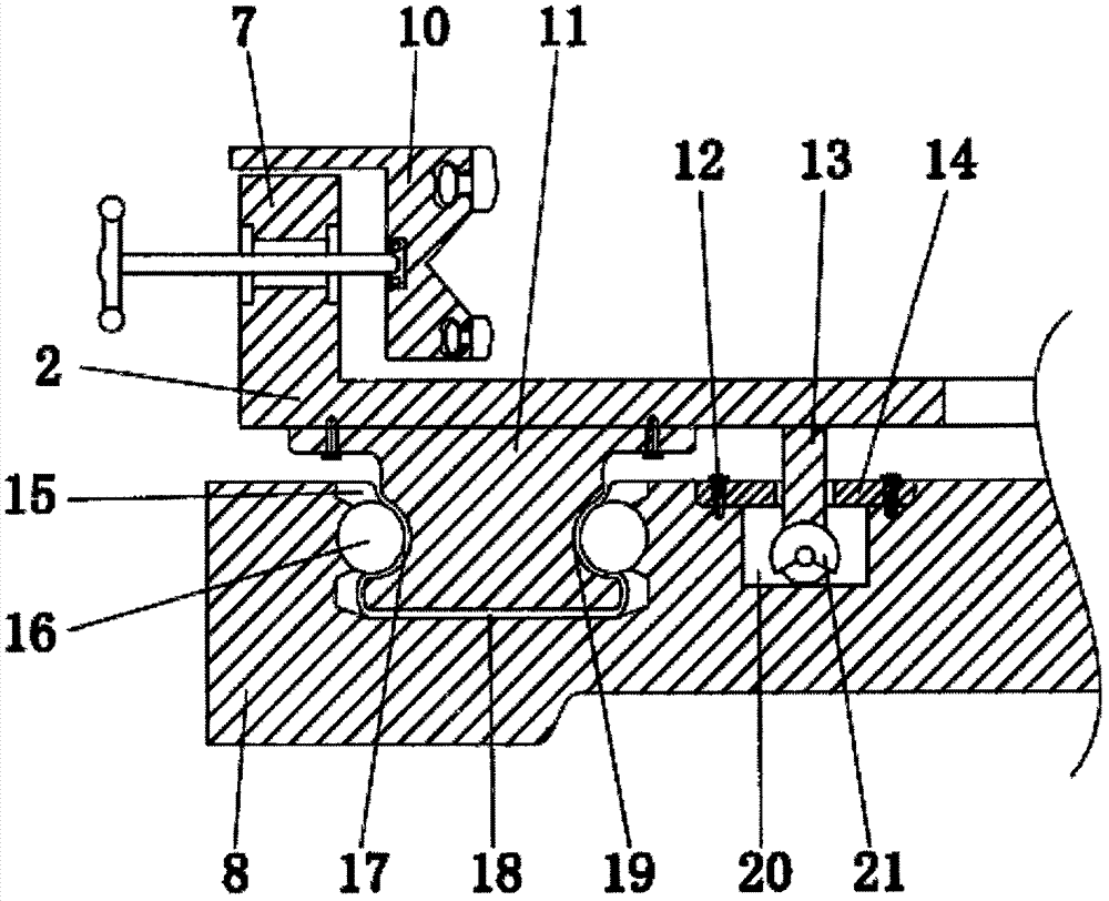
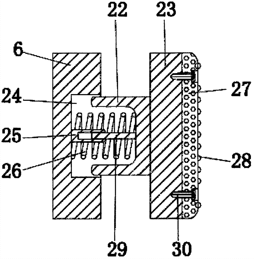
[0017] see Figure 1-4 , the present invention provides a technical solution: a mobile cutting machine, including a base 8, a cutting machine 5 is installed on the top of the base 8, a handle 1 is installed on the front side of the cutting machine 5, and a plate is provided on the front side of the top end of the base 8 Frame 2, a groove seat 3 is installed on the inner side of the top of the plate frame 2, and the inner side of the groove seat 3 is provided w...


PUM


Abstract

The invention discloses a mobile cutting machine, which comprises a base, a plate frame is arranged on the front side of the top end of the base, a groove seat is installed on the inner side of the top end of the plate frame, and a bottom bar is installed on the outside of the bottom end of the plate frame Shaped plate, the top outside of the base is provided with a bar-shaped groove, the bottom rear side of the plate frame is equipped with a rear baffle, the top front side of the plate frame is provided with an inner plate, the inner side of the inner plate Features splints. The mobile cutting machine, through the cooperation of the rear baffle, the splint and the bottom strip plate, pushes the plate frame to drive the bottom strip plate at the bottom to move in the strip groove on the base, and the ball rolls and moves on the ball when moving. In the groove, at the same time, it is convenient for the next step of cutting. The splint fixes the plate through the cooperation with the rear baffle. By setting the V-shaped groove, the plane on the outside of the splint can be clamped to the flat plate groove, and the cylinder can be clamped in the V-shaped groove. Plates and diamond-shaped plates increase the fixing effect on the plates, are less dangerous and have better use effects.

Description

technical field [0001] The invention relates to the technical field of cutting machines, in particular to a mobile cutting machine. Background technique [0002] The cutting machine is a tool that drives the blade through the transmission mechanism for cutting operations. It has the characteristics of safety, reliability, reasonable structure, and high work efficiency. It is suitable for cutting operations on materials such as stone and rigid materials. The cutting machine is manually adjusted during cutting. Placement position, such as an existing cutting machine, includes a housing, a blade cover connected to the housing, a handle, a motor is arranged in the housing, a blade is connected to the motor, the blade is located in the blade cover, and a lighting lamp is provided on the lower side of the housing. Although the cutting machine is designed with lights to facilitate night use, in actual use, it is not convenient for workers to adjust the cutting position and the next...

Claims


Application Information

Patent Timeline
IPC IPC(8): B23D19/00B23D33/02B23D33/00
CPCB23D19/00B23D33/00B23D33/02
Inventor 张志通徐淑辉朱翔
Owner 张志通
Learn More