Illuminating lamp device

A technology for lighting lamps and lamp holders, which is applied to lighting devices, fixed lighting devices, and components of lighting devices. It can solve problems such as potential safety hazards, electric shock accidents, cumbersome and complicated operations, etc., and achieve rapid installation and improve installation efficiency.

Active Publication Date: 2017-10-10
南通市莱特电气科技发展有限公司
View PDF6 Cites 1 Cited by
  • Summary
  • Abstract
  • Description
  • Claims
  • Application Information

AI Technical Summary

Problems solved by technology

[0002] In bridge construction, some lighting lamps are generally installed for bridge night lighting. However, these lighting lamps are generally fixed and connected by fastening bolts. , the operation is cumbersome and complicated, which greatly reduces the efficiency of maintenance. At the same time, the lamp holders of the existing bridge lighting lamps are generally connected to the mains. contact with conductive parts, it is very easy to cause electric shock accidents, and there is a great potential safety hazard

Method used


Image

  • Illuminating lamp device
  • Illuminating lamp device
  • Illuminating lamp device

Examples


Embodiment Construction

[0026] Combine below Figure 1-7 The present invention will be described in detail.

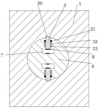
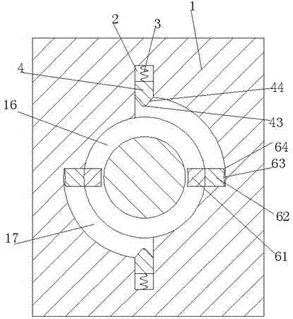
[0027] refer to Figure 1-7 , an illuminating lamp device according to an embodiment of the present invention, comprising a lamp holder and a lamp cap 21, the lamp holder 1 is provided with a turning hole with a notch facing right, and a turning member is rotatably installed in the turning hole 6. The upper and lower sides of the steering member 6 are correspondingly provided with a left and right connecting slot 7, a contact piece 8 is fixedly installed in the insertion slot 7, and a compression piece 11 is fixedly installed at the midpoint of the left end surface of the steering member 6 , and the left end surface of the compression piece 11 is provided with a hole, the lamp holder 1 is provided with an annular groove 16 at the left end of the turning hole, and a midpoint groove 15 is arranged at the midpoint of the left end of the annular groove 16, the The midpoint groove 15, the annula...


PUM


Abstract

An illuminating lamp device comprises a lamp holder and a lamp base. A turning hole with a rightward notch is formed in the lamp holder. A turning piece is rotatably mounted in the turning hole. A left insertion groove and a right insertion groove communicating with the left insertion groove are formed in the turning piece in a vertically corresponding mode. Wafers are fixedly mounted in the insertion grooves. A compression sheet is fixedly mounted on the midpoint of the left end face of the turning piece, and a hole is formed in the left end face of the compression sheet. An annular groove is formed in the portion, located at the left end of the turning hole, of the lamp holder, a midpoint groove is formed in the midpoint of the left end of the annular groove, and a horizontal sliding piece is mounted in the midpoint groove and can horizontally slide left and right in the midpoint groove. A fixing pin is fixedly mounted on the midpoint of the right end face of the horizontal sliding piece. A semicircular groove which is located behind and above the horizontal sliding piece and a semicircular groove located in front of and below the horizontal sliding piece are formed in the end wall of the annular groove. Pushing grooves which stretch up and down are arranged in the end wall of the annular groove in a vertically corresponding mode and communicate with the semicircular grooves. Charged sliding blocks are mounted in the pushing grooves in a horizontal sliding mode.

Description

technical field [0001] The invention relates to the field of bridges, in particular to a lighting device. Background technique [0002] In bridge construction, some lighting lamps are generally installed for bridge night lighting. However, these lighting lamps are generally fixed and connected by fastening bolts. , the operation is cumbersome and complicated, which greatly reduces the efficiency of maintenance. At the same time, the lamp holders of the existing bridge lighting lamps are generally connected to the mains. Contact with the conductive parts of the battery can easily cause electric shock accidents, and there is a great potential safety hazard. Contents of the invention [0003] The object of the present invention is to provide a lighting device for overcoming the above-mentioned defects in the prior art. [0004] A lighting device according to the present invention, comprising a lamp holder and a lamp cap, the lamp holder is provided with a turning hole with ...

Claims


Application Information

Patent Timeline
Patent Type & Authority Applications(China)
IPC IPC(8): F21S8/00F21V19/00F21V17/10F21V17/16F21Y115/10
CPCF21S8/00F21V17/10F21V17/164F21V19/0025F21Y2115/10
Inventor 斯幼云
Owner 南通市莱特电气科技发展有限公司
Why Eureka
Try Eureka