
A method and control system for power demand response to participate in distribution network voltage regulation

A technology of power demand response and voltage regulation, applied in the direction of power network operating system integration, AC network voltage regulation, information technology support system, etc., can solve problems such as inability to accurately participate in power grid regulation

Active Publication Date: 2019-08-30
HANGZHOU DIANZI UNIV
View PDF2 Cites 0 Cited by
  • Summary
  • Abstract
  • Description
  • Claims
  • Application Information

AI Technical Summary

Problems solved by technology

In order to make effective use of user-side demand response, the existing technology usually adopts the method of mandatory restriction of user-side demand (for example, government agencies, public institutions or office buildings have mandatory regulations: the temperature of the air conditioner should not be lower than 26 degrees during peak electricity consumption in summer) , although this method can play a role in regulating the power grid to a certain extent, there are uncertain factors in practice (mainly based on the user's compliance with the rules), and it is impossible to accurately participate in the regulation of the power grid

Method used


Image

  • A method and control system for power demand response to participate in distribution network voltage regulation
  • A method and control system for power demand response to participate in distribution network voltage regulation
  • A method and control system for power demand response to participate in distribution network voltage regulation

Examples


Embodiment Construction

[0061] Specific embodiments of the present invention will be described below in conjunction with the accompanying drawings, so as to describe the content of the present invention more clearly and completely. However, it should be noted that the described embodiment is only an embodiment of the present invention, not all embodiments.

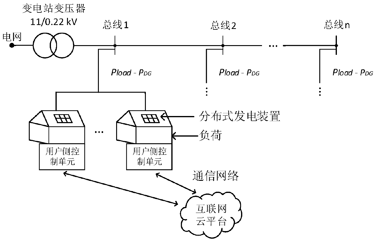
[0062] see figure 1 , which is a schematic diagram of the distribution network structure of the present invention. According to the present invention, a control system for power demand response participating in distribution network voltage regulation includes an Internet cloud platform and a user-side device installed at the user end and capable of accessing the Internet cloud platform through a communication network. The Internet cloud platform communicates with the user through the communication network. Side control unit for two-way communication.

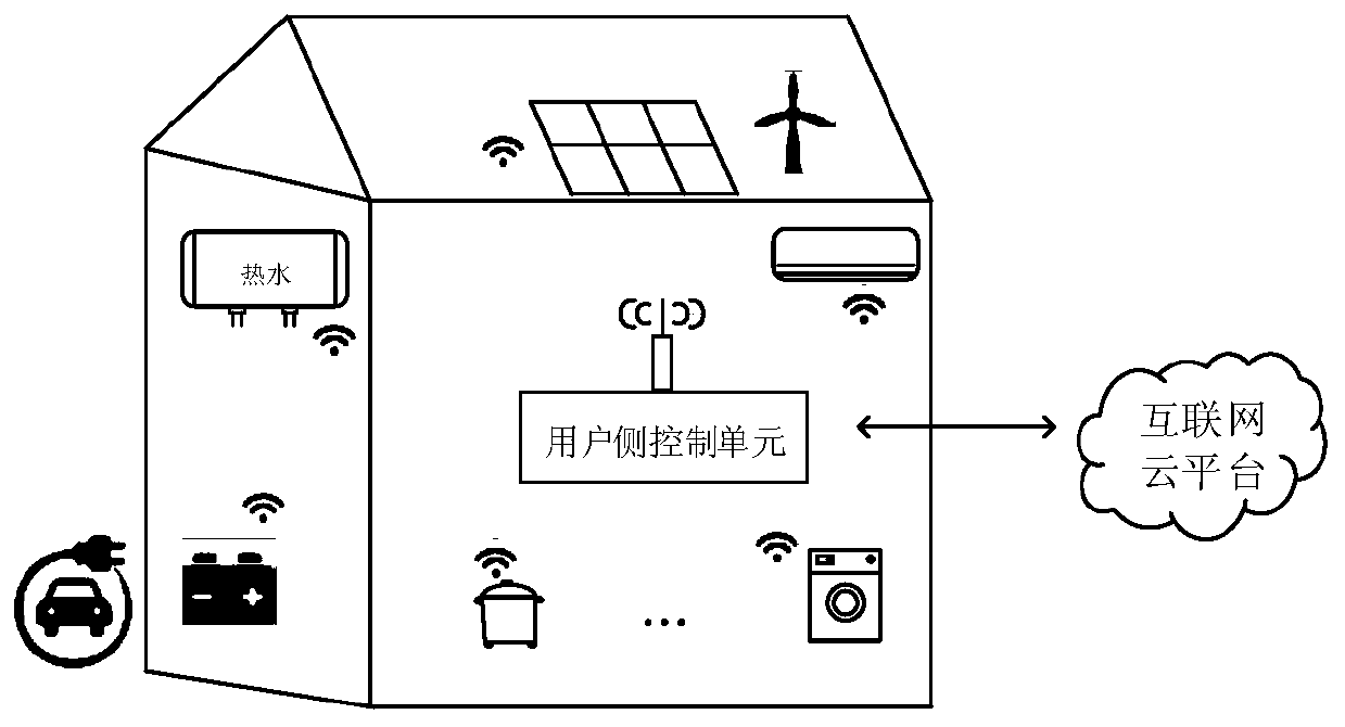
[0063] see figure 2 , which is a schematic structural diagram of a user-side device in the ...


PUM


Abstract

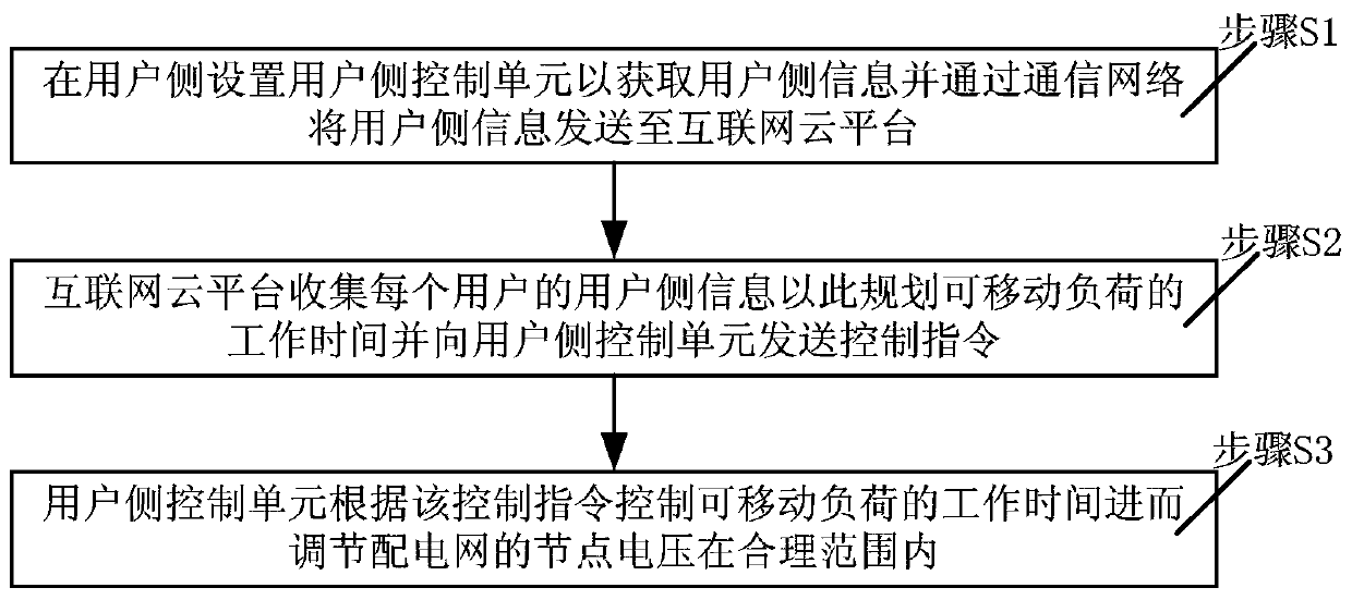
The invention discloses a method and control system for regulating voltage of a power distribution network through participation of electric power demand responses. The control system comprises an internet cloud platform and user side equipment that is arranged at the user side and can be accessed to the internet cloud platform through communication networks, wherein the user side equipment at least includes a user side control unit, a user side load and a user side distributed power generation device; and the internet cloud platform acquires non-movable load data, movable load data and distributed power generation data of a user, user node voltage and other information through the networks, takes the voltage stability, movable load demands and the like as constraint conditions, and takes user profit maximization as an objective function to establish an optimization model of user side demand responses. By adopting the technical scheme disclosed by the invention, the node voltage of the power distribution network can be controlled within a reasonable range through the planning of a movable load; and the problem of voltage rise caused by a large number of distributed grid connections and the problem of voltage drop caused by the simultaneous charging of a large number of electric vehicles can be solved, and the safe and stable operation of the power distribution network can be maintained.

Description

technical field [0001] The invention relates to the technical field of electric power demand response, specifically, a method and a control system for electric power demand response based on an Internet cloud platform to participate in distribution network voltage regulation. Background technique [0002] In order to reduce environmental pollution and deal with the problem of energy depletion. In recent years, the large-scale utilization of renewable energy such as solar energy and wind energy has become a major trend in the world's energy development. For example, the Danish government has set a goal of relying entirely on renewable energy for its energy supply by 2050. The U.S. Department of Energy proposes that renewable energy can meet 80% of U.S. electricity demand by 2050. my country is also vigorously developing renewable energy. However, the grid integration of large-scale renewable energy generation will affect the power quality and reduce the stability of the gr...

Claims


Application Information

Patent Timeline
Patent Type & Authority Patents(China)
IPC IPC(8): H02J3/14H02J3/38
CPCH02J3/003H02J3/14H02J3/382H02J2203/20H02J2310/64Y02B70/3225Y04S20/222
Inventor 谢强强徐志望秦会斌
Owner HANGZHOU DIANZI UNIV
Learn More