Lock and glove box
A technology of locks and lock rods, which is applied in the field of locks, can solve the problems that mechanical locks cannot meet the needs of market intelligence, and achieve the effect of simple structure, high reliability and reliable structure
- Summary
- Abstract
- Description
- Claims
- Application Information
AI Technical Summary
Problems solved by technology
Method used
Image

Examples
Embodiment 1
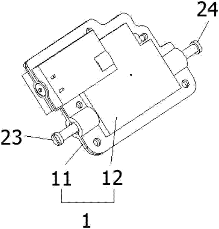
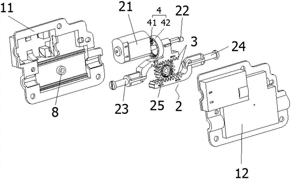
[0038] figure 1 It is a schematic structural diagram of the lock provided in Embodiment 1 of the present invention; figure 2 An exploded view of the structure of the lock provided in Embodiment 1 of the present invention; image 3 Schematic diagram of the structure of the lower cover provided for Embodiment 1 of the present invention; Figure 1-Figure 3 As shown, the lockset provided by Embodiment 1 of the present invention includes a housing 1 and a lock cylinder 2 installed in the housing 1;
[0039] The lock core 2 includes a driving mechanism 21, a cylindrical cam 22, a locking lever 1 23, a locking lever 2 24 and a rotating part 25;
[0040] The driving mechanism 21 is connected with the cylindrical cam 22;
[0041] The locking rod one 23 protrudes toward one side of the housing 1, and the locking rod one 23 is slidingly connected with the track of the cylindrical cam 22;
[0042] The second locking rod 24 protrudes to the other side of the housing 1 , and the second...
Embodiment 2
[0052] The lock provided in the second embodiment is a further improvement on the lock provided in the first embodiment. On the basis of the first embodiment, the lock provided in the second embodiment includes a housing 1 and a lock installed in the housing 1 core 2;
[0053] The lock core 2 includes a driving mechanism 21, a cylindrical cam 22, a locking lever 1 23, a locking lever 2 24 and a rotating member 25;
[0054] The driving mechanism 21 is connected with the cylindrical cam 22;
[0055] The locking rod one 23 protrudes toward one side of the housing 1, and the locking rod one 23 is slidingly connected with the track of the cylindrical cam 22;
[0056] The second locking rod 24 protrudes to the other side of the housing 1 , and the second locking rod 24 is connected to the first locking rod 23 through the rotating member 25 .
[0057] Preferably, the rotating member 25 is a transition gear, and the first lock bar 23 and the second lock bar 24 are respectively provi...
Embodiment 3
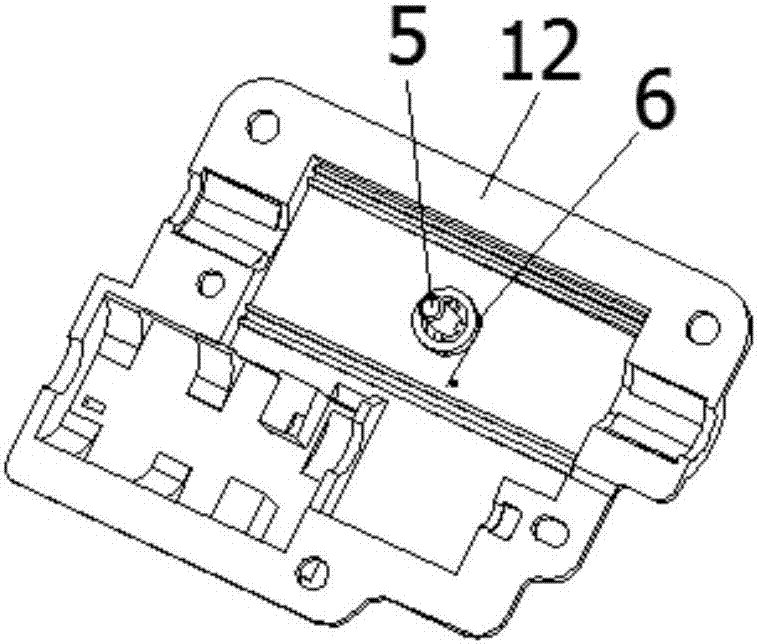
[0064] Figure 4 Schematic diagram of the structure of the lock provided in Embodiment 3 of the present invention; Figure 5 An exploded view of the structure of the lockset provided by Embodiment 3 of the present invention; Figure 6 Schematic diagram of the structure of the lower cover provided for the third embodiment of the present invention; as Figure 4-Figure 6 As shown, the lockset provided by Embodiment 3 of the present invention includes a housing 1 and a lock cylinder 2 installed in the housing 1;
[0065] The lock core 2 includes a driving mechanism 21, a cylindrical cam 22, a locking lever 1 23, a locking lever 2 24 and a rotating member 25;
[0066] The driving mechanism 21 is connected with the cylindrical cam 22;
[0067] The locking rod one 23 protrudes toward one side of the housing 1, and the locking rod one 23 is slidingly connected with the track of the cylindrical cam 22;
[0068] The second locking rod 24 protrudes to the other side of the housing 1 ...
PUM
 Abstract
Description
Claims
Application Information
 - Generate Ideas
- Intellectual Property
- Life Sciences
- Materials
- Tech Scout
- Unparalleled Data Quality
- Higher Quality Content
- 60% Fewer Hallucinations
Browse by: Latest US Patents, China's latest patents, Technical Efficacy Thesaurus, Application Domain, Technology Topic, Popular Technical Reports.
© 2025 PatSnap. All rights reserved.Legal|Privacy policy|Modern Slavery Act Transparency Statement|Sitemap|About US| Contact US: help@patsnap.com