
Sensitivity testing system and testing method of wavelength phase shifting algorithm

A technology of sensitivity testing and wavelength phase shifting, which is applied in the field of optical detection, can solve problems such as difficulty in promoting phase shifting, errors, and influence on measurement results, and achieve a simple and convenient test system, solve the problem of phase shifting algorithm precision calibration test, and high precision Effect

Active Publication Date: 2019-10-11
SHANGHAI UNIV
View PDF8 Cites 0 Cited by
  • Summary
  • Abstract
  • Description
  • Claims
  • Application Information

AI Technical Summary

Problems solved by technology

The hardware phase shifting technology represented by PZT, in the process of phase shifting, will inevitably produce changes in mechanical stress and introduce errors, thus affecting the actual measurement results
Especially when the interferometer system is large, it will be difficult to drive the phase shift, and the non-linear motion will introduce a large error[3]
In addition, the hardware phase-shifting technology algorithm cannot overcome the shadow of the parasitic fringes formed by multi-surface interference [4], and it is necessary to smear Vaseline and other measures to eliminate the parasitic fringes, which will introduce errors to the measurement, and the wavelength phase-shifting technology can overcome the above shortcomings.

Method used


Image

  • Sensitivity testing system and testing method of wavelength phase shifting algorithm
  • Sensitivity testing system and testing method of wavelength phase shifting algorithm

Examples


Embodiment Construction

[0015] The present invention will be described in detail below in conjunction with the accompanying drawings and preferred embodiments.

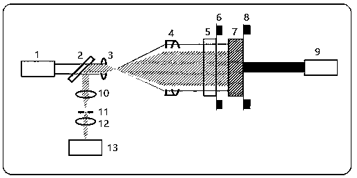
[0016] like figure 1 As shown, a wavelength phase shift algorithm sensitivity test system includes a wavelength tuning laser 1, a half mirror 2, a lens 3, a collimating mirror 4, a reference mirror 5, a piezoelectric ceramic 6, a test piece 7, Piezoelectric ceramic two 8, laser Doppler interferometer 9, lens two 10, aperture 11, lens three 12 and CCD 13; the wavelength tuning laser 1 can realize scanning within a certain wavelength range, and the beam emitted by the wavelength tuning laser 1 After passing through the half mirror 2, the lens one 3, and the collimating mirror 4, it reaches the reference mirror 5, a part of the light is reflected back from the reference mirror 5, and the other part of the light passes through the reference mirror 5 and reaches the surface of the measured object 7 and is reflected back; The light reflected back...


PUM


Abstract

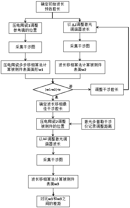
The invention relates to a sensitivity test system and method based on a wavelength phase shifting algorithm. Lasers emitted by a wavelength tuning laser are reflected back from a to-be-tested piece and a reference mirror in an optical path system and have interference, a CCD receives interference lasers returned from the to-be-tested piece and the reference mirror and records interference light intensity. The position of the reference mirror is adjusted by piezoelectric ceramic I according to hardware phase shifting principle, and surface form W1 of the to-be-tested piece is measured; surface form W2 of the to-be-tested piece is measured by changing wavelength according to the wavelength phase shifting algorithm. Interference cavity length when|W2-W1| is the minimum is determined. The position of the to-be-tested piece is adjusted by piezoelectric ceramic II, and the moving distance L of the piezoelectric ceramic II is recorded by a laser Doppler interferometer. Surface form W3 of the to-be-tested piece after the piezoelectric ceramic II moves for L is analyzed on the basis of the wavelength phase shifting algorithm, whether the difference between the surface forms W3 and W2 measured before and after adjustment of the piezoelectric ceramic II is consistent with the moving distance L of the piezoelectric ceramic II is analyzed, so that the wavelength phase shifting algorithm precision is obtained, and the purpose of calibration of measurement precision is achieved.

Description

technical field [0001] The invention relates to a sensitivity test system and a test method of a wavelength phase-shifting algorithm, belonging to the field of optical detection. Background technique [0002] Optical interference detection technology is a measurement and testing method based on the principle of light wave interference. It is recognized as one of the most effective and accurate means for detecting optical components and optical systems. The interferometer adopts interference detection technology to realize non-contact measurement at the wavelength level, and has higher sensitivity and better usability than other types of detection instruments. The phase-shifting interferometry that appeared in the 1970s produced a phase shift through the modulation of the interference field, and then recovered the physical quantity to be measured according to several phase-shifted interferograms collected, which significantly improved the accuracy and automation of interferom...

Claims


Application Information

Patent Timeline
Patent Type & Authority Patents(China)
IPC IPC(8): G01B11/24G01B9/02
Inventor 董焰章孙涛于瀛洁牟柯冰
Owner SHANGHAI UNIV
Learn More