A mechanical device capable of quantitative thread take-up for textile use

A mechanical device and take-up shaft technology, which is applied in the directions of transportation and packaging, function indication, and delivery of filamentous materials, etc. It can solve the problems of low degree of automation, difficult disassembly and manufacturing, and affects the speed of take-up, and achieves stable performance. And the effect of high safety performance, enhanced internal structure and strength, and improved work efficiency

Active Publication Date: 2019-02-22
河北南冠科技有限公司
View PDF9 Cites 0 Cited by
  • Summary
  • Abstract
  • Description
  • Claims
  • Application Information

AI Technical Summary

Problems solved by technology

[0006] However, the existing wire take-up device has the following problems: 1. The existing wire take-up device has a low degree of automation, and cannot automatically control the wire take-up time according to the amount of wire taken up, and resource waste often occurs;
[0007] 2. The existing wire take-up device is complex in structure and bulky, not easy to disassemble and operate, which will greatly affect the speed of wire take-up, making it difficult to improve the efficiency of wire take-up and reduce work efficiency;
[0008] 3. The existing wire take-up device is usually directly fixed on the operating table. During the wire take-up process, it is usually driven by a motor to rotate, and its vibration and noise are relatively obvious;
[0009] 4. During the take-up process of the existing wire take-up device, due to the rotation of the motor, the internal heat generation is large. In order to accelerate the heat dissipation, it is necessary to add a heat dissipation component separately, which is time-consuming, laborious and costly;
[0010] 5. The overall structure of the take-up drum in the existing take-up device is complex and bulky, it is not easy to disassemble and manufacture, and it is difficult to apply in the take-up

Method used


Image

  • A mechanical device capable of quantitative thread take-up for textile use
  • A mechanical device capable of quantitative thread take-up for textile use
  • A mechanical device capable of quantitative thread take-up for textile use

Examples


Embodiment Construction

[0073] The following will be combined with Figure 1-Figure 12 The present invention is described in detail, and the technical solutions in the embodiments of the present invention are clearly and completely described. Apparently, the described embodiments are only some of the embodiments of the present invention, not all of them. Based on the embodiments of the present invention, all other embodiments obtained by persons of ordinary skill in the art without making creative efforts belong to the protection scope of the present invention.

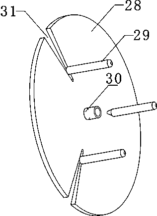
[0074] The present invention provides a kind of mechanical device that can realize quantitative take-up for weaving through improvement, such as Figure 1-Figure 12 As shown, it can be implemented in the following manner; the device includes a take-up control box 1, a take-up drum 2, a take-up control bearing base plate 3, and a take-up control elastic support mechanism 4; the take-up control box 1 is integrally fixed on the take-up The lin...


PUM


Abstract

The invention discloses a textile mechanical device capable of realizing quantitative wire take-up. The device includes a wire take-up control box, a wire take-up drum, a wire take-up control bearing base plate, and a wire take-up control elastic support mechanism; the invention can automatically realize the wire take-up operation , and can achieve fast winding, greatly improving work efficiency, saving labor, high stability and safety performance. This device can set the rotation time of the take-up rotating motor according to the amount of take-up, so as to obtain the work time of take-up suitable for the amount of take-up; it will not waste resources due to equipment idling; when the take-up starts, the take-up roller is placed on the main take-up On the spool, and close to the iron sheet; make it easy to disassemble and assemble between the take-up drum and the main take-up shaft; when the equipment is not in use, its volume can be reduced without taking up too much space; when the take-up is completed, the take-up The take-up drum position push rod in the wire drum position pushing mechanism moves from left to right, which is used to drive the wire take-up drum to automatically separate from the iron sheet, so that the wire take-up drum can be easily removed.

Description

technical field [0001] The invention relates to the related field of textiles, in particular to a mechanical device for textiles that can realize quantitative thread take-up. Background technique [0002] At present, the textile field belongs to a very important field, and the thread take-up device is an indispensable operating equipment; however, the thread reel is used to drive the reel to drive the thread take-up, and the existing reel is small, and it is generally operated by a single person The wire reel takes up the wire, and the efficiency is low. [0003] After searching, it was found that the utility model with the patent number CN201120015148.4 discloses a metal microwire take-up shaft for textiles, which relates to a textile machine. It consists of a take-up tube and end panels at both ends; the take-up tube is a circular tube, and the inner hole of the circular tube is a mounting hole. The end panel is circular, and the inner surface of the end panel has a cert...

Claims


Application Information

Patent Timeline
Patent Type & Authority Patents(China)
IPC IPC(8): B65H54/40B65H63/08
CPCB65H54/40B65H63/08B65H2513/512B65H2220/02
Inventor 姚巧宁张萌萌张辉
Owner 河北南冠科技有限公司
Why Eureka
Try Eureka