Wooden cupboard
A technology for cabinets and base cabinets, applied in the field of cabinets, can solve the problems of difficult operation by operators, small washing space and cooking space, etc., and achieve the effects of simple and convenient operation, good operation space, and good user experience.
- Summary
- Abstract
- Description
- Claims
- Application Information
AI Technical Summary
Problems solved by technology
Method used
Image
Examples
Embodiment 1
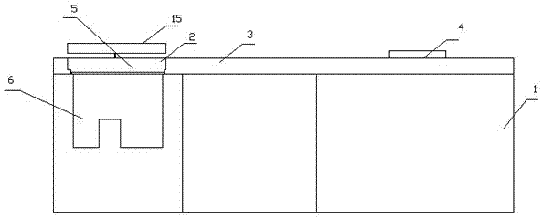
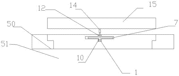
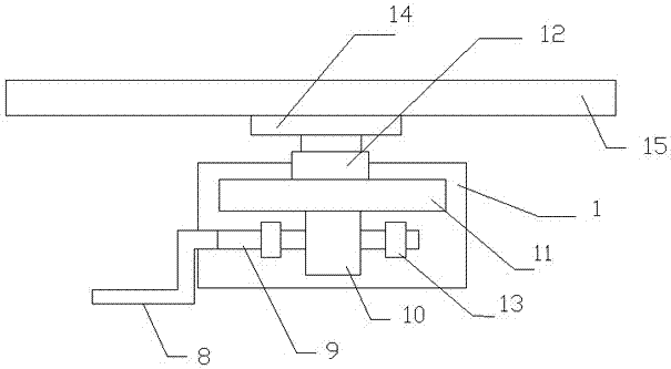
[0022] This embodiment includes a base cabinet 1, the base cabinet 1 is provided with a washing area 2, a cooking area 3 and a cooking area 4, the cooking area is located between the washing area and the cooking area, the washing area is provided with a washing tank 5, and the washing tank 5 A stainless steel water basin 6 is installed, and a hood cooker is installed in the cooking area. It is characterized in that: the washing tank 5 includes an upper tank 50 and a lower tank 51. In the lower groove 51, the base cabinet 1 is provided with a strip groove 7, the strip groove 7 is perpendicular to the upper groove 50, and the handle 8, the rotating shaft 9, the gear 10, the rack 11 and the cylinder are installed in the base cabinet 1. 12. The rotating shaft 9 is installed in the base cabinet 1 through the bearing 13, the gear 10 is sleeved on the rotating shaft 9, the handle 8 is connected to the rotating shaft, the handle 8 is a Z-shaped handle, and the teeth, 11 are installed i...
Embodiment 2
[0024] This embodiment includes a base cabinet 1, the base cabinet 1 is provided with a washing area 2, a cooking area 3 and a cooking area 4, the cooking area is located between the washing area and the cooking area, the washing area is provided with a washing tank 5, and the washing tank 5 A stainless steel water basin 6 is installed, and a hood cooker is installed in the cooking area. It is characterized in that: the washing tank 5 includes an upper tank 50 and a lower tank 51. In the lower groove 51, the base cabinet 1 is provided with a strip groove 7, the strip groove 7 is perpendicular to the upper groove 50, and the handle 8, the rotating shaft 9, the gear 10, the rack 11 and the cylinder are installed in the base cabinet 1. 12. The rotating shaft 9 is installed in the base cabinet 1 through the bearing 13, the gear 10 is sleeved on the rotating shaft 9, the handle 8 is connected to the rotating shaft, the handle 8 is a Z-shaped handle, and the teeth, 11 are installed i...
Embodiment 3
[0027] On the basis of Embodiment 1 or Embodiment 2, shafts 18 are installed on the left and right sides of the strip groove 7, and a plurality of baffle plates 16 and a plurality of coil springs 17 are sleeved on one shaft 18, and a baffle plate 16 is equipped with a volute spring 17, and the baffle plate 16 on the shaft 18 on the left and right sides is mutually correspondingly arranged, and one end of the volute spring 17 is connected on the baffle plate 16, and the other end is connected on the shaft 18. Through the function of the baffle, the cross-shaped bar groove can be blocked to prevent dust from falling into the bar-shaped groove and contaminating the rack. When the rack and the connecting plate move forward or backward, the baffle plays the role of the spiral spring The bottom is automatically lapped on the top of the bar groove to prevent dust.
PUM
 Abstract
Description
Claims
Application Information
 - R&D
- Intellectual Property
- Life Sciences
- Materials
- Tech Scout
- Unparalleled Data Quality
- Higher Quality Content
- 60% Fewer Hallucinations
Browse by: Latest US Patents, China's latest patents, Technical Efficacy Thesaurus, Application Domain, Technology Topic, Popular Technical Reports.
© 2025 PatSnap. All rights reserved.Legal|Privacy policy|Modern Slavery Act Transparency Statement|Sitemap|About US| Contact US: help@patsnap.com


