
Cable fixing device

A fixing device and cable technology, applied in the field of electric power, can solve problems such as switch cabinet burnout, overall equipment damage, and support insulation damage, and achieve the effects of convenient operation, simple structure, and protection from stress damage

Pending Publication Date: 2017-09-08
WEIHAI POWER SUPPLY COMPANY OF STATE GRID SHANDONG ELECTRIC POWER COMPANY
View PDF0 Cites 0 Cited by
  • Summary
  • Abstract
  • Description
  • Claims
  • Application Information

AI Technical Summary

Problems solved by technology

[0002] In the field of electric power, the high-voltage switchgear uses inflatable and environmentally friendly gases. The solid switchgear can’t bear the stress brought by the cable because of the connection pile head, which will cause damage to the support insulation, cause the switchgear to burn, and cause damage to the overall equipment. This kind of hidden danger has become a prominent hidden danger with the construction of smart grid

Method used


Image

  • Cable fixing device
  • Cable fixing device
  • Cable fixing device

Examples


Embodiment Construction

[0016] The specific embodiments of the present invention will be further described below in conjunction with the accompanying drawings.

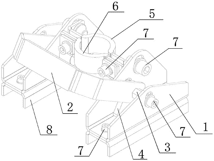
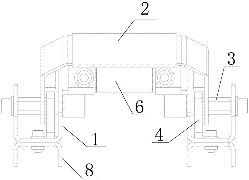
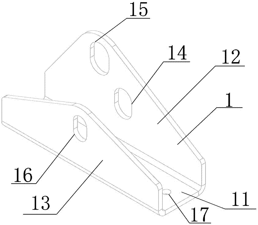
[0017] Such as Figure 1-6 As shown, the cable fixing device involved in the present invention includes two symmetrically arranged bases 1, and each base 1 includes a bottom plate 11, and an inner side plate 12 and an outer side plate 13 are arranged opposite to each other on the bottom plate 11. The inner panel 12 is provided with a first waist-shaped hole 14 and a second waist-shaped hole 15, and the outer panel 13 is provided with a third waist-shaped hole 16; the cable fixing device also includes a cable clamping mechanism, the The cable clamping mechanism includes a connected first arc-shaped pinch plate 5 and a second arc-shaped pinch plate 6, and the cable is clamped between the first arc-shaped pinch plate 5 and the second arc-shaped pinch plate 6, the The first arc gusset 5 is connected between two second waist-shaped holes 15; the...


PUM


Abstract

The invention provides a cable fixing device. The cable fixing device comprises two bases which are symmetrically arranged, wherein each base comprises a base plate respectively; an inner side plate and an outer side plate are oppositely arranged on the base plate; a first waist-shaped hole and a waist-shaped hole are formed in the inner side plate, and a third waist-shaped groove is formed in the outer side plate. The device also comprises a cable clamping mechanism, the mechanism comprises a first arc-shaped buckle plate and a second arc-shaped buckle plate which are connected, and the first arc-shaped buckle plate is connected between the two second waist-shaped holes; a connecting shaft is arranged between the first waist-shaped hole and the third waist-shaped hole of each base, the inner end part of each connecting shaft is arranged on the inner side of the corresponding inner side plate, and an up-and-low linkage mechanism is formed with the cable clamping mechanism; the outer end part of each connecting shaft is arranged at the position of the corresponding third waist-shaped hole, a connecting piece is connected with each connecting shaft through the outer end part of each connecting shaft, and the middle section of each prism-shaped connecting shaft is arranged between the corresponding first waist-shaped hole and the corresponding third waist-shaped hole; and the middle section of each connecting shaft is connected with a cam and a handle. The device can be used for stably jacking a cable so as to protect a switch cable lug from being damaged by stress.

Description

technical field [0001] The invention relates to the field of electric power, in particular to a cable fixing device. Background technique [0002] In the field of electric power, the high-voltage switchgear uses inflatable and environmentally friendly gases. The solid switchgear can’t bear the stress brought by the cable because of the connection pile head, which will cause damage to the support insulation, cause the switchgear to burn, and cause damage to the overall equipment. This kind of hidden danger has become a prominent hidden danger with the construction of smart grid. Contents of the invention [0003] In order to solve the problems existing in the prior art, the present invention proposes a cable fixing device to protect the switch terminal from stress damage. [0004] In order to achieve the above object, the present invention proposes a cable fixing device, which includes two symmetrically arranged bases, each base includes a bottom plate, and an inner side p...

Claims


Application Information

Patent Timeline
Patent Type & Authority Applications(China)
IPC IPC(8): H02B1/20
CPCH02B1/202
Inventor 周子程孙明李维娜张睿毕高丽郑永威荣俊兴冷小洁王伟卢媛赵慧群冯逊
Owner WEIHAI POWER SUPPLY COMPANY OF STATE GRID SHANDONG ELECTRIC POWER COMPANY
Learn More