
Acoustic sensor for monitoring rock burst

An acoustic sensor and rockburst technology, applied in scientific instruments, instruments, seismology, etc., can solve problems such as undeliverable, easy to wear out cables or acoustic emission probes, time-consuming and labor-intensive problems, to ensure coupling effect and enhance monitoring The effect on forecast reliability

Active Publication Date: 2017-09-01
SICHUAN UNIV
View PDF9 Cites 0 Cited by
  • Summary
  • Abstract
  • Description
  • Claims
  • Application Information

AI Technical Summary

Problems solved by technology

The use of this device has the following disadvantages: ①Because the distance between the fixed installation device and the wall of the borehole is very close, it is necessary for the fixed installation device and the borehole to be basically concentric in structure, and the wall of the hole needs to be smooth, but these requirements in actual construction Difficult to guarantee; ②Due to the large size of the fixed installation device, it is only suitable for drilling with a large diameter, resulting in an increase in drilling costs; ③The entire transmission rod and installation device are inserted into the drill hole by force and rigidly. Not only is the friction force high, it is easy to wear the cable or the acoustic emission probe, but it is also easy to be stuck in the drill hole and cannot be sent to the place where it needs to be installed; Therefore, the installation process is not only time-consuming and labor-intensive, but also has extremely low work efficiency; ⑤Because the wall of the borehole is a cylindrical surface, and the end face of the acoustic emission probe is a plane, how to ensure that the end face of the acoustic emission probe is effectively coupled with the wall of the borehole is also a problem in practical applications. problem to be solved
[0007] Based on the disadvantages and defects in the above-mentioned various implementation methods, the application and promotion of acoustic emission detection in the monitoring of rock (body) stability and rockburst dynamic disasters is limited to a certain extent.
[0008] Therefore, how to install the acoustic emission probe in the borehole conveniently and effectively, and how to effectively couple the installed acoustic emission probe with the hole wall is still a difficult point in field monitoring and research at present, and there is a lack of relevant testing methods and technical support

Method used


Image

  • Acoustic sensor for monitoring rock burst
  • Acoustic sensor for monitoring rock burst
  • Acoustic sensor for monitoring rock burst

Examples


Embodiment 1

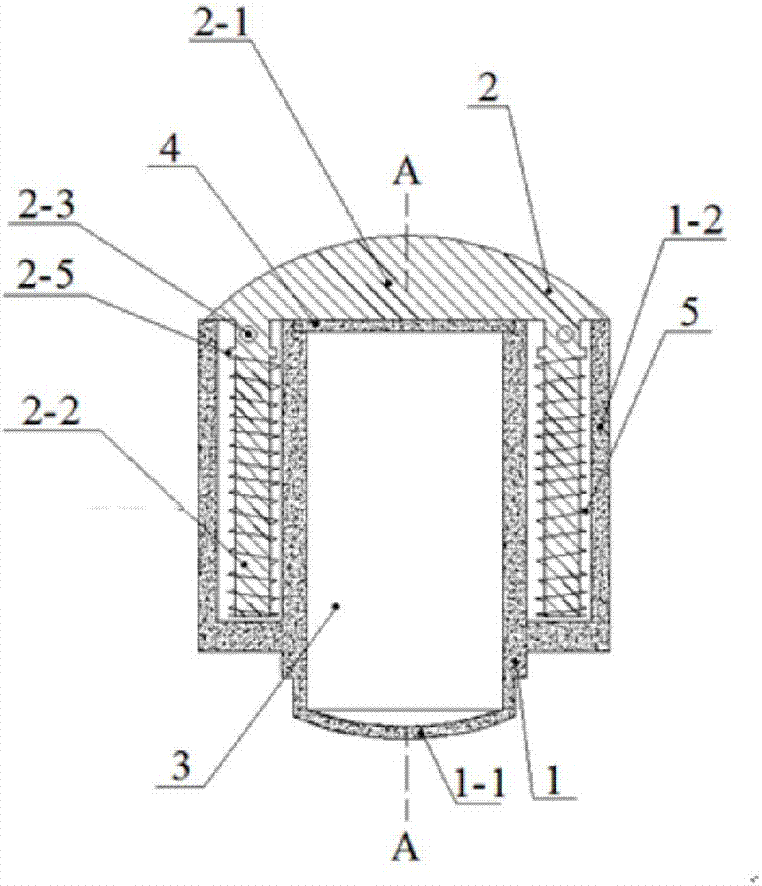
[0050] The rockburst monitoring acoustic sensor that present embodiment provides, as figure 1 As shown, the acoustic emission probe 3, the probe installation mechanism and the combination of the acoustic emission probe and the probe installation mechanism are transmitted to the transmission mechanism set in the borehole of the monitored rock mass; the probe installation mechanism and the acoustic emission probe 3 The quantity is one.

[0051] like Figure 4 , Figure 5 As shown, the above-mentioned acoustic emission probe 3 is a cylindrical structure with a cable connector 3-1 extending from the side, and one end of the acoustic emission probe is coated with butter.

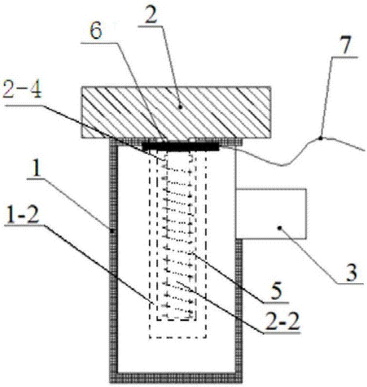
[0052] like Figure 1 to Figure 3 As shown, the above-mentioned probe installation mechanism is mainly composed of a sleeve assembly 1, a guide assembly 2, an end cover 4, a spring 5, a limit pin 6 and a connecting assembly.

[0053] like figure 2 , image 3 and Figure 6 As shown, the above-mentioned sle...

Embodiment 2

[0064] The acoustic sensor for rockburst monitoring provided in this embodiment is composed of an acoustic emission probe, a probe installation mechanism, and a transmission mechanism that transmits the combination of the acoustic emission probe and the probe installation mechanism to the set position in the borehole of the monitored rock mass; The number of the mechanism and the acoustic emission probe are both one.

[0065] The transmission mechanism provided in this embodiment is the same as the transmission mechanism provided in Embodiment 1.

[0066] The probe installation mechanism provided in this embodiment is basically the same as the probe installation mechanism given in Embodiment 1. In view of this embodiment, the guide assembly 2 and the sleeve are realized through the pluggable connection between the guide assembly 2 and the end cover 4. The moving direction of the barrel assembly 1 is controlled. In this embodiment, certain improvements are made to the structure...


PUM


Abstract

The invention discloses an acoustic sensor for monitoring rock burst. The acoustic sensor comprises an acoustic emission probe, a probe installation mechanism and a transmission mechanism, wherein the transmission mechanism is used for a combination body of the acoustic emission probe and the probe installation mechanism to a set position in a drilling hole of a to-be-monitored rock body; the probe installation mechanism is mainly formed by a sleeve assembly, a guiding assembly, an end cover and a spring; the guiding assembly is in pluggable connection with the sleeve assembly or the end cover; the assembled probe installation mechanism is used for locking the acoustic emission probe in a probe sleeve of the sleeve assembly; the spring in an elastic sleeve of the sleeve assembly is in a compression state. According to the acoustic sensor for monitoring rock burst, disclosed by the invention, through pluggable connection and matching between the guiding assembly and the sleeve assembly or the end cover and by utilizing the action of an elastic restoring force of the spring, the control to a movement direction of the guiding assembly and a probe assembly is realized, so that the problem of effective installing and coupling of the acoustic emission probe is solved, and not only can the acoustic emission probe be conveniently transmitted, but also the coupling effect of the acoustic emission probe and the wall of the drilling hole can be ensured.

Description

technical field [0001] The invention belongs to the technical field of rock (body) engineering safety monitoring in engineering construction, and relates to an acoustic sensor for rockburst monitoring. Background technique [0002] Rock (body) deformation and damage during engineering construction, especially rockburst dynamic disasters, will directly endanger the safety of the project and even cause catastrophic effects. Therefore, effective monitoring and monitoring of rock (body) stability and rockburst dynamic disasters Forecasting is one of the important contents of engineering safety construction. At present, as an important means of non-destructive monitoring, acoustic emission is used in the monitoring and forecasting of rock (body) stability and rockburst dynamic disasters in engineering construction. [0003] During the excavation and construction of surrounding rocks in underground engineering, in order to accurately predict the possible deformation and damage of...

Claims


Application Information

Patent Timeline
IPC IPC(8): G01V1/20
CPCG01V1/20G01V2210/1429G01V1/181G01V1/166
Inventor 刘建锋邓朝福裴建良王璐徐慧宁邓建辉
Owner SICHUAN UNIV
Learn More