
Novel grain conveyor convenient to move

A technology of conveyors and conveying mechanisms, applied in the direction of conveyors, conveyor objects, transportation and packaging, etc., can solve the problems of operator injury, environmental pollution, immovability, etc., and achieve the effect of simple and effective adjustment and convenient use

Active Publication Date: 2017-09-01
无为皖江粮食机械有限公司
View PDF5 Cites 6 Cited by
  • Summary
  • Abstract
  • Description
  • Claims
  • Application Information

AI Technical Summary

Problems solved by technology

[0002] my country's grain consumption is huge, so grain transportation is relatively frequent. At present, belt conveyors are usually used in the grain transportation process. Most of the existing belt conveyors are fixed conveyors, that is, belt conveyors The position is generally immovable. Under normal circumstances, the grain is transported to the feeding end of the belt conveyor, and then the grain is lifted to the discharge end. After the erection is completed, the lifting height is fixed and cannot be changed. , In addition, when the grain is poured into the feeding end of the conveyor and lifted, a large amount of light and fine impurities and dust in the grain will float into the air, resulting in a large amount of dust when the grain is put into storage, and a large amount of dust floating in the air to the operation Personnel bring bodily harm and also cause pollution to the environment. At the same time, a large amount of light and fine impurities and dust are transported into the warehouse or transported together with the grain.

Method used


Image

  • Novel grain conveyor convenient to move

Examples


Embodiment Construction

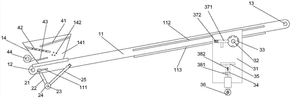
[0018] refer to figure 1 As shown, a novel grain conveyor that is convenient to move proposed by the present invention includes a conveying mechanism, a moving auxiliary mechanism and a height adjustment mechanism;

[0019] The conveying mechanism includes a conveying frame 11, a first transmission shaft 12, a second transmission shaft 13 and a conveyor belt. The first transmission shaft 12 is rotatably mounted on the first end of the conveying frame 11, and the second transmission shaft 13 is rotatably mounted on the conveying frame 11. At the second end, the conveyor belt is sleeved on the first transmission shaft 12 and the second transmission shaft 13;

[0020] The mobile auxiliary mechanism comprises the first slide block 21, the first connecting rod 22, the mounting shaft 23, the first roller 24 and the second connecting rod 25, and the transport frame 11 is provided with the first slide block 21 on the first transmission shaft 12 and The first chute 111 that moves betw...


PUM


Abstract

The invention puts forward a novel grain conveyor convenient to move. The novel grain conveyor convenient to move comprises a conveying mechanism, a moving assistance mechanism and a height adjustment mechanism. The conveying mechanism comprises a conveying rack, a first transmission shaft, a second transmission shaft and a conveying belt. The moving assistance mechanism comprises a first sliding block, a first connecting rod, a mounting shaft, a first roller and a second connecting rod, and a first sliding groove allowing the first sliding block to move between the first transmission shaft and the second transmission shaft is formed in the conveying rack. The height adjustment mechanism comprises a second sliding block, a mounting rack, a first rotating shaft, a gear, a first rotary plate, a second rotating shaft, a second rotary plate and a second roller, and a second sliding groove allowing the second sliding block to move between the first sliding groove and the second transmission shaft is formed in the conveying rack. The novel grain conveyor is convenient to use, and the position of the feed end and the position of the discharge end can be simply and effectively adjusted.

Description

technical field [0001] The invention relates to the field of agricultural transportation equipment, in particular to a novel grain conveyor which is convenient to move. Background technique [0002] my country's grain consumption is huge, so grain transportation is relatively frequent. At present, belt conveyors are usually used in the grain transportation process. Most of the existing belt conveyors are fixed conveyors, that is, belt conveyors The position is generally immovable. Under normal circumstances, the grain is transported to the feeding end of the belt conveyor, and then the grain is lifted to the discharge end. After the erection is completed, the lifting height is fixed and cannot be changed. , In addition, when the grain is poured into the feeding end of the conveyor and lifted, a large amount of light and fine impurities and dust in the grain will float into the air, resulting in a large amount of dust when the grain is put into storage, and a large amount of du...

Claims


Application Information

Patent Timeline
Patent Type & Authority Applications(China)
IPC IPC(8): B65G21/12B65G41/00B65G69/18B65G69/12
CPCB65G21/12B65G41/002B65G41/008B65G69/12B65G69/186B65G2201/042
Inventor 凌姗姗
Owner 无为皖江粮食机械有限公司
Learn More