Annular unmanned aerial vehicle and aerial photography device thereof
A UAV, ring-shaped technology, applied in the field of UAVs, can solve the problems of heavy workload, unable to see the scenery of UAVs, incompetent, etc., to achieve the effect of convenient aerial photography and aerial photography
- Summary
- Abstract
- Description
- Claims
- Application Information
AI Technical Summary
Problems solved by technology
Method used
Image
Examples
Embodiment 1
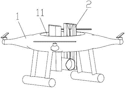
[0028] Such as figure 1 As shown, a ring-shaped unmanned aerial vehicle includes a body 1. The center of the body 1 is provided with a cavity 11 vertically penetrating through the body 1, and an aerial photography device 2 is provided in the cavity 11. The aerial photography device 2 can shoot upwards and downwards in the cavity 11, thereby realizing upward and downward shooting.
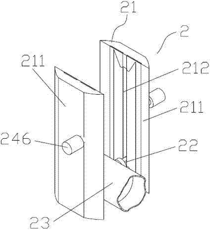
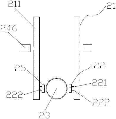
[0029] Such as figure 2 , image 3 and Figure 4 As shown, the aerial photography device 2 includes a vertical platform 21 fixed on the inner wall of the cavity 11, the vertical platform 21 is provided with a rotary drive mechanism 22 that vertically lifts along the vertical platform 21, and the rotary drive mechanism 22 is controlled by the lifting mechanism. 24 drives up and down, and the rotation drive mechanism 22 is connected with a camera 23 , and the camera 23 is connected with a locator 25 . The rotation driving mechanism 22 is used to drive the camera 23 to rotate, so as to change the ...
Embodiment 2
[0034] Such as figure 2 , image 3 and Figure 4 Shown, a kind of aerial photographing device of ring-shaped unmanned aerial vehicle comprises the vertical platform 21 that is fixed on the body of annular drone, and vertical platform 21 is provided with the rotating drive mechanism that vertically lifts along vertical platform 21 22 , the rotation drive mechanism 22 is driven up and down by the lifting mechanism 24 , the rotation drive mechanism 22 is connected with a camera 23 , and the camera 23 is connected with a locator 25 . The rotation driving mechanism 22 is used to drive the camera 23 to rotate, thereby changing the shooting angle of the camera 23 , and the locator 25 is used to position the camera 23 , so as to monitor the specific position of the camera 23 in real time. According to actual needs, the locator 25 is a GPS locator or / and a Beidou locator.
[0035]The vertical platform 21 includes two guide rails 211 arranged opposite to each other, and the two guid...
PUM
 Abstract
Description
Claims
Application Information
 - Generate Ideas
- Intellectual Property
- Life Sciences
- Materials
- Tech Scout
- Unparalleled Data Quality
- Higher Quality Content
- 60% Fewer Hallucinations
Browse by: Latest US Patents, China's latest patents, Technical Efficacy Thesaurus, Application Domain, Technology Topic, Popular Technical Reports.
© 2025 PatSnap. All rights reserved.Legal|Privacy policy|Modern Slavery Act Transparency Statement|Sitemap|About US| Contact US: help@patsnap.com


