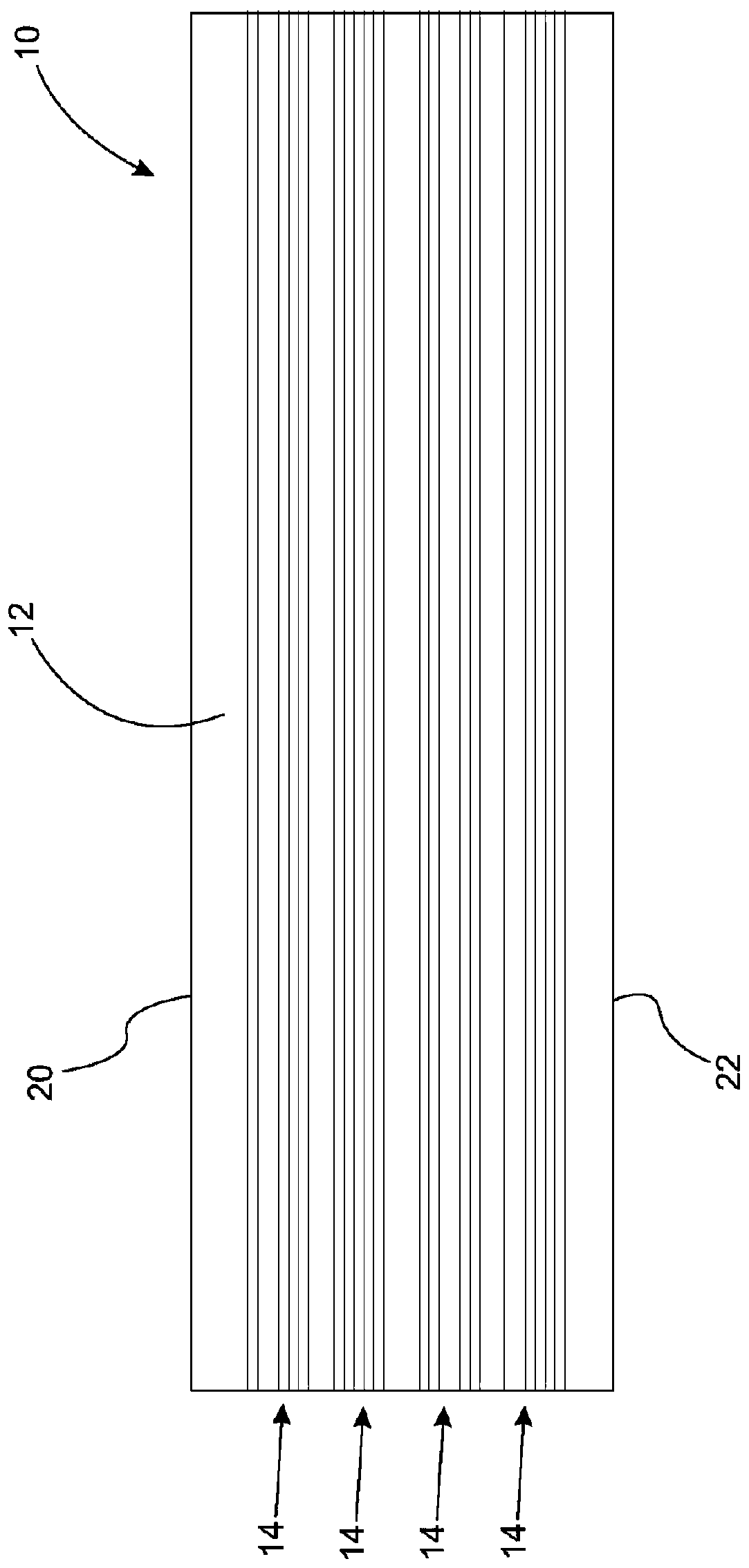
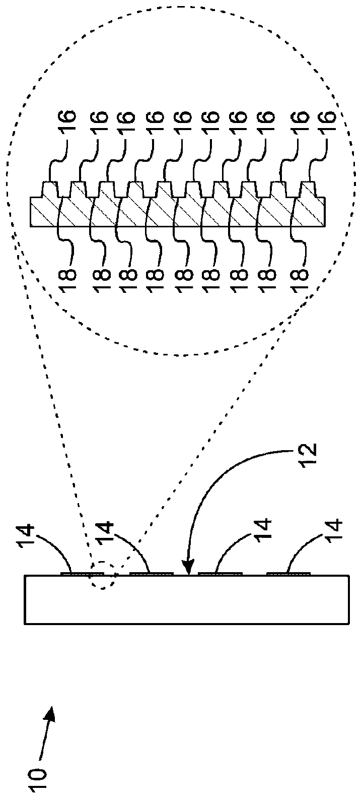
Diffraction imaging of grooved structures on optical bands
A technology of grooves and light strips, applied in the direction of scattering characteristic measurement, optical test flaws/defects, systems characterized by carrier shapes, etc., can solve problems that do not extend to light strips, etc.
- Summary
- Abstract
- Description
- Claims
- Application Information
AI Technical Summary
Problems solved by technology
Method used
Image

Examples
Embodiment Construction
[0022] Reference will now be made in detail to presently preferred compositions, embodiments and methods of the invention which, so far as the inventors know, constitute the best modes for practicing the invention. The drawings are not necessarily to scale. It is to be understood, however, that the disclosed embodiments are merely examples of the invention that can be embodied in various and alternative forms. Therefore, specific details disclosed herein are not to be interpreted as limiting, but merely as a representative basis for any aspect of the invention or as a representative basis for teaching one skilled in the art to variously employ the invention.
[0023] Except in examples, or where otherwise expressly indicated, all numerical quantities in this description indicating amounts of material or conditions and / or uses of reactions are to be understood as describing the broadest scope of the invention The word "approximately" is modified. Practice within the indicated...
PUM
| Property | Measurement | Unit |
|---|---|---|
| wavelength | aaaaa | aaaaa |
Abstract
Description
Claims
Application Information
 - R&D
- Intellectual Property
- Life Sciences
- Materials
- Tech Scout
- Unparalleled Data Quality
- Higher Quality Content
- 60% Fewer Hallucinations
Browse by: Latest US Patents, China's latest patents, Technical Efficacy Thesaurus, Application Domain, Technology Topic, Popular Technical Reports.
© 2025 PatSnap. All rights reserved.Legal|Privacy policy|Modern Slavery Act Transparency Statement|Sitemap|About US| Contact US: help@patsnap.com