Eureka AIR delivers breakthrough ideas for toughest innovation challenges, trusted by R&D personnel around the world.

Fluid transfer device, system and method

A fluid transmission and transmission device technology, applied in the field of fluid sampling devices, can solve problems such as easy to be forgotten, dependent cleaning process, pollution, etc.

Pending Publication Date: 2017-08-29
MILLIPORE CORP
View PDF4 Cites 6 Cited by
  • Summary
  • Abstract
  • Description
  • Claims
  • Application Information

AI Technical Summary

Problems solved by technology

[0003] Traditional cleaning procedures are operator dependent and can be easily forgotten or performed incorrectly
Additionally, to obtain a sample, the operator needs to connect to the system twice with a different sampling device, multiplying the potential for contamination

Method used


Image

  • Fluid transfer device, system and method
  • Fluid transfer device, system and method
  • Fluid transfer device, system and method

Examples


Embodiment Construction

[0026] Various embodiments of fluid transfer devices, systems and methods are described. It is to be understood that the invention is not limited to particular embodiments described, as such may, of course, vary. An aspect described in connection with a particular embodiment is not necessarily limited to that embodiment, and can be practiced in any other embodiment.

[0027] All technical and scientific terms used herein, unless defined otherwise, have the meaning commonly understood by one of ordinary skill in the art. As used in the specification and the appended claims, unless the context clearly requires otherwise, the singular forms "" an" and "the" include plural referents. Unless the context clearly requires otherwise, the terms "or" " means a non-exclusive "or". In the following description, well-known components or steps may not be described in detail in order to avoid unnecessarily obscuring the embodiments of the present invention.

[0028] As used herein, the phr...


PUM


Abstract

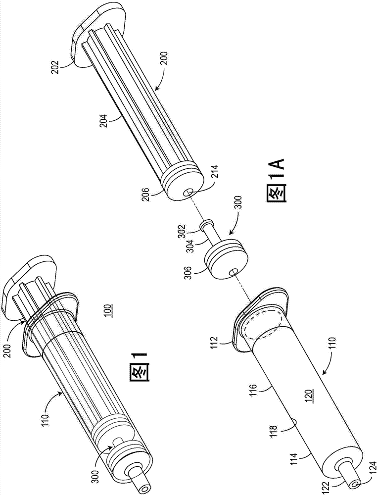
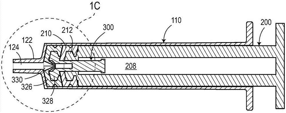
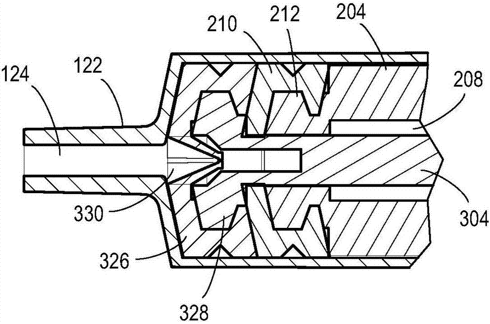
A fluid transfer device includes a syringe barrel having a chamber, a first plunger slidably movable inside the chamber, and a second plunger slidably movable inside the chamber. The distal end portion of the first plunger is engageable with the proximal end portion of the second plunger such that when the distal end portion of the first plunger and the proximal end portion of the second plunger are engaged, the second plunger is movable by the first plunger. A check valve may be incorporated into the distal end portion of the second plunger to allow a fluid to pass therethrough in a direction towards the proximal end portion of the second plunger and prevent a fluid to pass therethrough in a reverse direction. A fluid transfer assembly and a sampling method are also described.

Description

technical field [0001] Embodiments of the invention generally relate to fluid delivery devices, systems and methods. In particular, various embodiments of fluid sampling devices and methods are described. Background technique [0002] In pharmaceutical, biotechnology, food, beverage, and other industries, it is often desirable to take many samples to monitor process progress and / or optimize process steps. Conventional fluid sampling is typically performed with needle-free sampling valves connected to reactors or other process vessels via small diameter tubing. The operator first wipes the connection of the sampling valve with a cleaning agent, typically an alcohol or methanol solution. Next, connect the standard syringe, withdraw sufficient sample, disconnect, and discard the standard syringe. Do this to empty the pipes and valves of any dead legs that are causing inaccurate readings. Subsequently, the sampling valve was cleaned again, and a new syringe was attached to t...

Claims


Application Information

Patent Timeline
IPC IPC(8): A61B5/15A61M5/178A61M5/31A61M5/315B01L3/00G01N1/14
CPCA61B5/15003A61B5/150221A61B5/150236A61B5/150244A61B5/150251A61B5/150992A61M5/1782A61M5/3129A61M5/31501B01L3/502G01N1/14B01L2300/0832B01L2300/0864B01L2400/0478B01L2400/0611B01L2200/141A61B5/153A61M2005/3132A61M2005/3128B01L3/56B01L2400/0475
Inventor J·马尔登R·兰比格勒
Owner MILLIPORE CORP
Why Eureka
Eureka Blog
Learn More