
A Simple Method for Measuring the Sweep Angle of the Wing

A technology of sweep angle and wings, applied in the direction of angle/taper measurement, etc., can solve the problems of equipment, expensive equipment, high measurement environment requirements, etc., and achieve the effect of easy implementation, saving measurement cost and low measurement cost

Active Publication Date: 2019-11-19
CHINA AEROSPACE TIMES ELECTRONICS CORP
View PDF5 Cites 0 Cited by
  • Summary
  • Abstract
  • Description
  • Claims
  • Application Information

AI Technical Summary

Problems solved by technology

Since the three-coordinate instrument or three-dimensional measuring machine is expensive, difficult to transport, and has high requirements for the measurement environment, it is impossible to equip each aerial bomb with a three-dimensional coordinate instrument or three-dimensional measuring machine in the field environment, so a simple method is needed Capable of measuring wing sweep angle

Method used


Image

  • A Simple Method for Measuring the Sweep Angle of the Wing
  • A Simple Method for Measuring the Sweep Angle of the Wing
  • A Simple Method for Measuring the Sweep Angle of the Wing

Examples


Embodiment

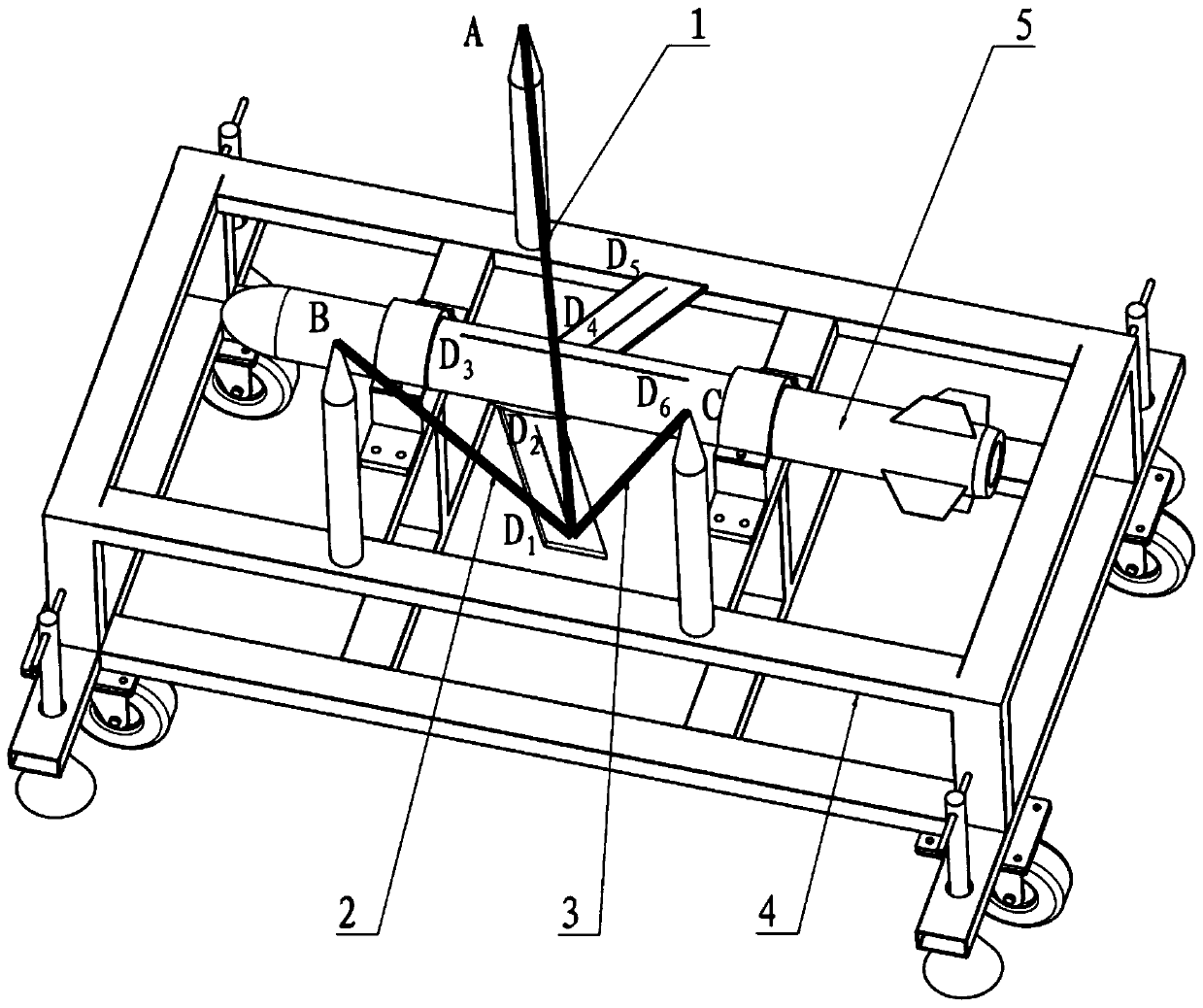
[0035] Such as figure 2 As shown, the aerial bomb 5 is fixed on the trolley 4, it is necessary to measure the leading edge sweep angles of the left wing and the right wing of the aerial bomb 5, and obtain the confidence interval corresponding to the leading edge sweep angle of the left wing and the right wing with a confidence level of 99.74%.

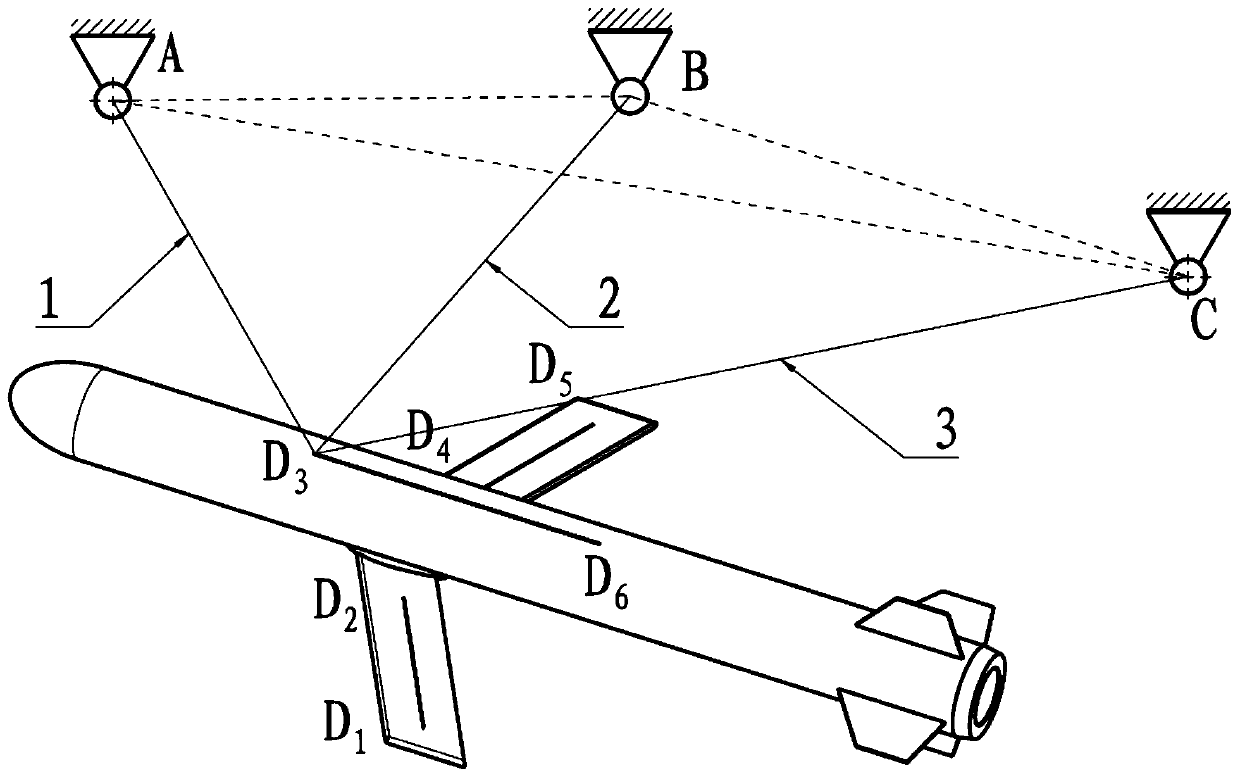
[0036] In the production stage, the left and right wings of the bomb 5 have been engraved with D 1 D. 2 and D 4 D. 5 ,D 1 D. 2 and D 4 D. 5 They are respectively parallel to the leading edges of the left and right wings; the engraved line D on the body of the bomb 5 3 D. 6 ,D 3 D. 6 parallel to the longitudinal axis of the projectile.

[0037] According to the method of the present invention, three poles are installed on the trolley 4, and the vertices of the three poles are respectively A, B, and C, and the three points of A, B, and C are used as the reference points for measurement, and the first rope 1. One end of the s...


PUM


Abstract

The present invention provides a simple method for measurement of the sweepback angles of a missile wing. Three datum points A, B and C which are not located on the same line are arranged at the upper of the missile wing, lines are scribed on the missile wing and a projectile body, a rope and a ruler are employed to measure the distances among the datum points and the distances between the datum points to the Dk; a coordinate system is built in a plane ABC; and the space coordinate values of all the feature points Dk and the sweepback angles of the missile wing are obtained through calculation according to the geometric equation, and the confidence interval of the sweepback angles of the missile wing is calculated according to the measurement precision of the ruler. The simple method for measurement of sweepback angles of the missile wing employs common tools to measure the sweepback angles of the missile wing, is easy to realize and is not high in the requirement of the measurement environment, and is very suitable for measurement of the sweepback angles of the missile wing in the field conditions; the simple method for measurement of sweepback angles of the missile wing can replace an expensive three dimensional measuring machine or a three-dimensional measurement machine to measure the sweepback angles of the missile wing so as to observably save the measurement cost; and the simple method for measurement of sweepback angles of the missile wing can calculate the confidence interval of the sweepback angles of the missile wing so as to provide reference data for an emission decision.

Description

technical field [0001] The invention relates to a simple method for measuring the sweep angle of a wing, and is especially suitable for measuring the sweep angle of the wing by using common tools such as ropes and dimensions under field conditions lacking precision measuring instruments after long-distance transportation. Background technique [0002] The sweep angle of the bomb wing is extremely important for the range and strike accuracy of the aerial bomb. After long-distance transportation, the sweep angle of the wings is easily affected by shock and vibration and deviates from the design value. Therefore, in the field environment after long-distance transportation, it is generally necessary to measure the sweep angle of the wings before launching. [0003] In engineering, a three-dimensional coordinate instrument or a three-dimensional measuring machine is generally used to measure the sweep angle of the wing. Since the three-coordinate instrument or three-dimensional...

Claims


Application Information

Patent Timeline
Patent Type & Authority Patents(China)
IPC IPC(8): G01B5/24
CPCG01B5/24
Inventor 罗志辉王卫平宓铁良刘海静许昌林任郭湛宇
Owner CHINA AEROSPACE TIMES ELECTRONICS CORP
Learn More