Cleaning liquid spraying device and cleaning liquid spraying method

A technology of spraying device and spraying method, which is applied in the direction of spraying device, spraying device, cleaning method and utensils, etc., can solve the problems such as the deterioration of the appearance of the steel plate surface, and achieve the effect of preventing nozzle clogging and suppressing spraying

Active Publication Date: 2019-09-10
JFE STEEL CORP
View PDF7 Cites 0 Cited by
  • Summary
  • Abstract
  • Description
  • Claims
  • Application Information

AI Technical Summary

Problems solved by technology

As a result, in the annealing furnace, indentations are generated on the surface of the steel sheet, so the appearance of the steel sheet surface deteriorates

Method used


Image

  • Cleaning liquid spraying device and cleaning liquid spraying method
  • Cleaning liquid spraying device and cleaning liquid spraying method
  • Cleaning liquid spraying device and cleaning liquid spraying method

Examples


Embodiment approach 1

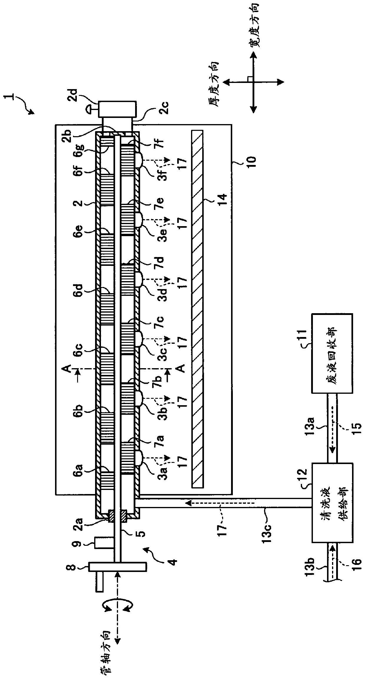
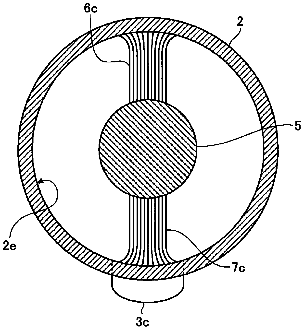
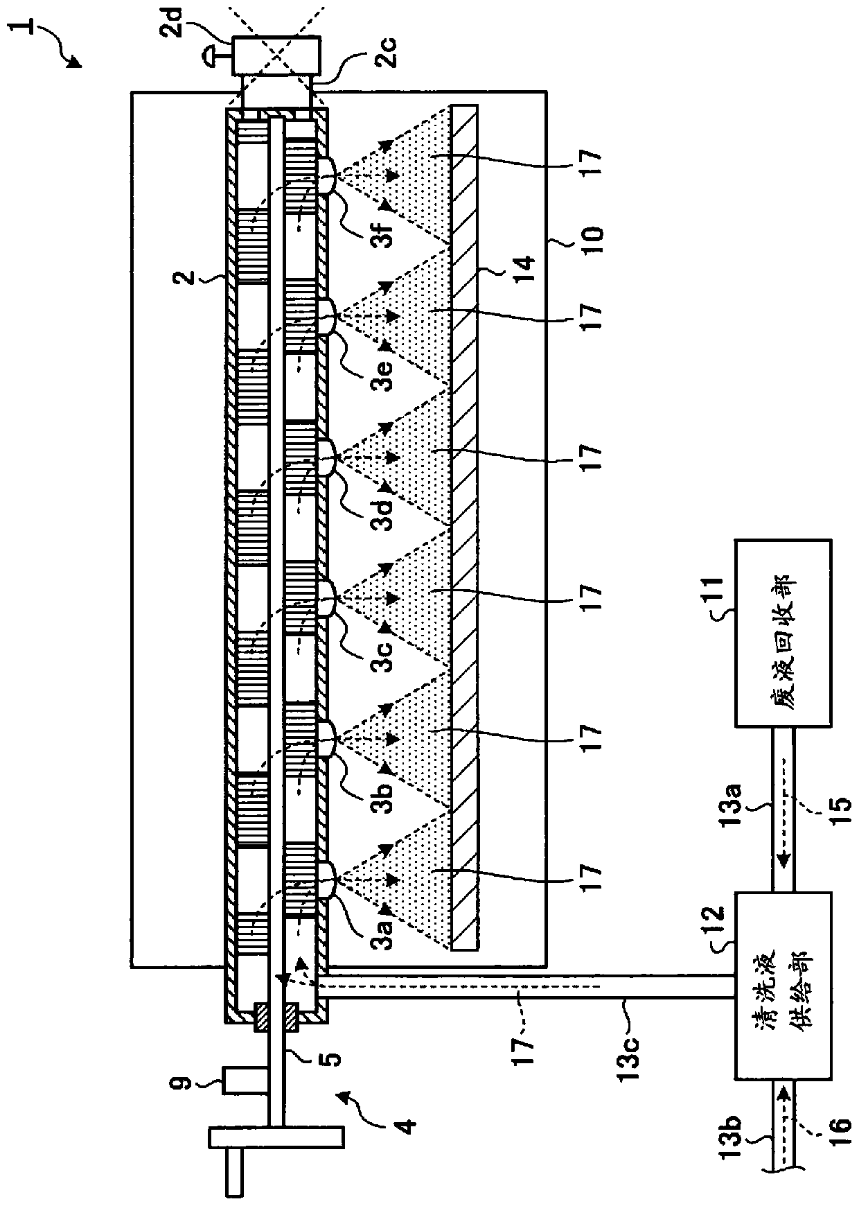
[0029] First, the configuration of the cleaning liquid spraying device according to Embodiment 1 of the present invention will be described. figure 1 It is a diagram showing a configuration example of the cleaning liquid spraying device according to the embodiment of the present invention. figure 2 is showing figure 1 A cross-sectional view along line A-A of the schematic structure inside the spray piping of the cleaning liquid spraying device shown. like figure 1 , 2 As shown, the cleaning liquid injection device 1 according to the embodiment of the present invention includes: a spray pipe 2 provided with spray nozzles 3 a to 3 f for spraying a cleaning liquid 17 ; and a rotary brush 4 for cleaning the inside of the spray pipe 2 and the magnetization portion 9, which magnetizes the rotating shaft 5 of the rotating brush 4 appropriately. In addition, the cleaning liquid injection device 1 includes: a housing 10 forming a cleaning space for performing a cleaning process; a...

Embodiment approach 2

[0073] Next, Embodiment 2 of the present invention will be described. In the first embodiment described above, the hard magnet (permanent magnet, etc.) of the magnetized portion 9 that switches the rotating shaft 5 of the rotating brush 4 between a magnetized state and a non-magnetized state is arranged outside the rotating shaft 5, but in the second embodiment , a hard magnet for switching between a magnetized state and a non-magnetized state is provided inside the rotating shaft of the rotating brush 4 .

[0074] on the one hand, Figure 8 It is a diagram showing a configuration example of a cleaning liquid spraying device according to Embodiment 2 of the present invention. like Figure 8 As shown, the cleaning liquid spraying device 21 according to the second embodiment includes a rotating shaft 25 instead of the rotating shaft 5 of the rotating brush 4 of the cleaning liquid spraying device 1 according to the first embodiment described above, and a magnetized part 29 ins...


PUM


Abstract

A cleaning fluid spray device according to an embodiment of the present invention is provided with: a circulation tube for circulating cleaning fluid to a spray nozzle; a rotating brush for cleaning internal parts of this circulation tube; and a magnetizing unit for magnetizing a rotating shaft for this rotating brush. The rotating brush has: the rotating shaft, which rotates centered in the axial direction of the circulation tube; and brushes provided along the longitudinal direction of this rotating shaft. In the cleaning fluid spray device, magnetic contaminants in the cleaning fluid present within the circulating tube are attracted to the rotating shaft magnetized by the magnetizing unit, the magnetic contaminants eliminated from this cleaning fluid, and the cleaning fluid after elimination of the magnetic contaminants sprayed onto a metal plate surface of an object to be cleaned from the spray nozzle.

Description

technical field [0001] The present invention relates to a cleaning liquid spraying device and a cleaning liquid spraying method for spraying a cleaning liquid onto the surface of a metal plate to be cleaned. Background technique [0002] Conventionally, in a production line of a steel sheet such as a thin plate, a cleaning step of cleaning the surface of the rolled steel sheet is performed before a predetermined step such as an annealing step. In general, rolling oil and iron powder adhere to the surface of the rolled steel sheet. In the cleaning step, for example, spraying a cleaning liquid onto the surface of the steel sheet using a spray device and brushing the surface of the steel sheet by rotating a brush roll removes adhering rolling oil and iron powder from the surface of the steel sheet to be cleaned. [0003] In addition, in the cleaning step, water at a predetermined pressure is sprayed onto the surface of the steel sheet subjected to spraying of cleaning liquid a...

Claims


Application Information

Patent Timeline
Patent Type & Authority Patents(China)
IPC IPC(8): B08B9/04B05B1/20B05B15/50B08B3/02
CPCB08B3/02B08B9/04
Inventor 松坂直树谷本庆太藤原诚熊野晴彦
Owner JFE STEEL CORP
Why Eureka
Try Eureka