
A conductive slip ring with two contact functions of rotation and slip ring at the same time

A conductive slip ring, conductive ring technology, applied in the directions of non-rotating current collectors, rotating current collectors, connections, etc., can solve problems such as the inability to meet the transmission of various signals, achieve the transmission of electrical signals, widen application fields, The effect of simplifying the internal structure

Active Publication Date: 2018-12-21
BEIJING PULIMEN ELECTRO MECHANICAL HIGH TECHN CO
View PDF3 Cites 0 Cited by
  • Summary
  • Abstract
  • Description
  • Claims
  • Application Information

AI Technical Summary

Problems solved by technology

[0003] Conventional conductive slip rings use rolling bearings as the support between the stator and the rotor to realize the relative rotation between the stator and the rotor, thereby realizing the transmission of various signals within the relative rotation range of 360° between the stator part and the rotor part, but the distance between the rotor and the stator The axial displacement is 0, which cannot satisfy the transmission of various signals between two parts that not only have relative rotation but also have relative axial displacement

Method used


Image

  • A conductive slip ring with two contact functions of rotation and slip ring at the same time
  • A conductive slip ring with two contact functions of rotation and slip ring at the same time

Examples


Embodiment Construction

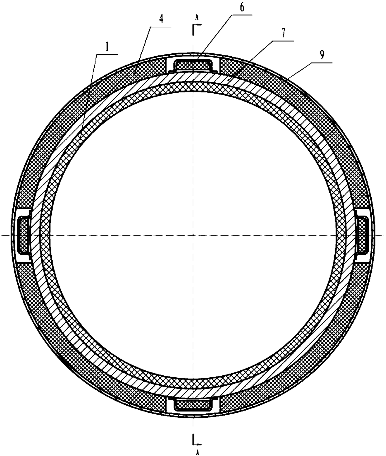
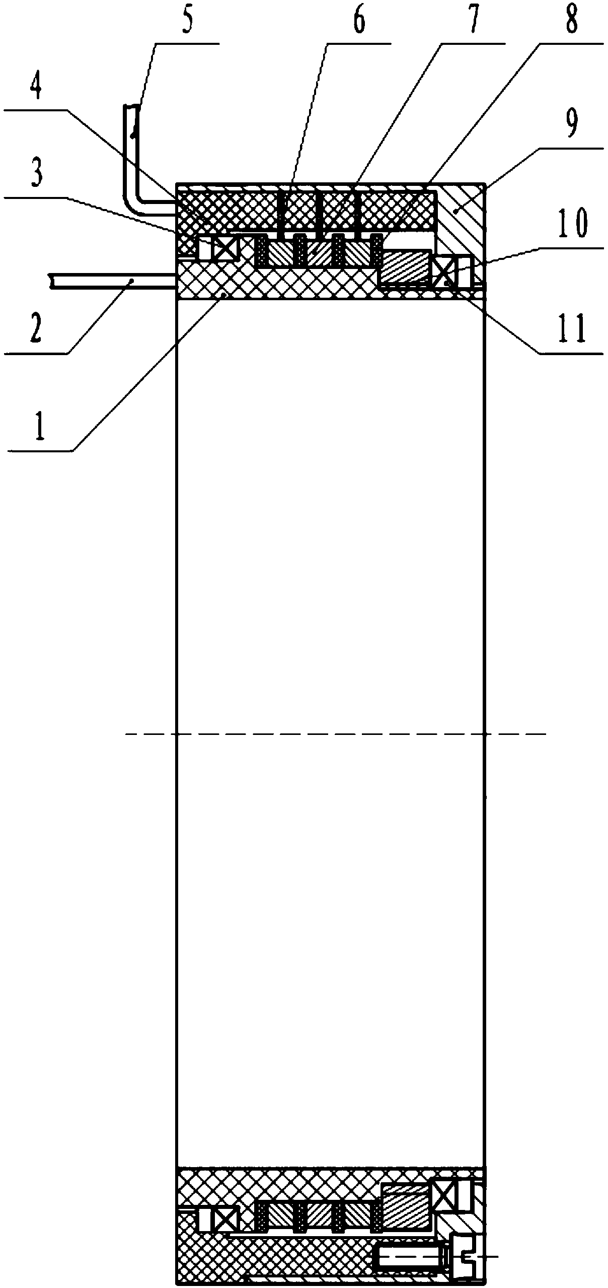
[0021] Such as figure 1 , figure 2 As shown, the conductive ring 7 and the insulating ring 8 welded with the rotor wire 2 are installed on the rotor shaft 1 of the conductive slip ring, and the rotor wire 2 is drawn out from the lead groove on the rotor shaft 1; and the conductive ring 7 and the insulating ring 8 Assembling, one side is fixed with a top nut 10, and the other side is close to the raised structure of the side wall of the rotor shaft 1.

[0022] After installing the sliding bearing I3 on ​​one side of the rotor shaft 1, install the stator frame 4, and ensure that the two-way axial sliding displacement is more than 0.5mm each, and they can rotate freely within 360°.

[0023] The brush 6 welded with the stator wire 5 that is in sliding contact and rotational contact with the conductive ring 4 is installed on the stator frame 4, and fixed with epoxy glue. The stator wire 5 is drawn out from the lead groove on the stator frame 4.

[0024] After installing the slid...


PUM


Abstract

The invention relates to a conductive slip ring simultaneously enabling a rotation contact function and a slip ring contact function. The conductive slip ring comprises a conductive ring, an insulating ring and the like; the conductive ring and the insulating ring sleeve a rotor shaft; the conductive ring and the insulating ring are assembled at intervals; one end of the rotor shaft is provided with a sliding bearing I; a stator frame sleeves the rotor shaft; axial two-way slide and 360-degree rotation between the stator frame and the rotor shaft can be realized through the sliding bearing I; an electric brush installation slot is formed in the stator frame along the circumferential direction of the stator frame; an electric brush is installed in the electric brush installation slot; an end portion of the electric brush contacts with the conductive ring; the other end of the rotor shaft is provided with a sliding bearing II; and an outer cover sleeves the stator frame; and axial two-way slide and 360-degree rotation between the outer cover and the rotor shaft is realized through the sliding bearing II; and the outer cover is fixedly connected with the stator frame. With the conductive slip ring of the invention adopted, the transmission problem of a plurality of signals in simultaneous rotation and slide between two components can be solved.

Description

technical field [0001] The invention relates to a conductive slip ring. Background technique [0002] A conductive slip ring is a device that transmits current and its signal, which transmits the current and its signal from a stationary part to another rotating part. Among them, multiple conductive rings are the rotating parts of the conductive slip ring. The brush is installed on the stator part of the conductive slip ring. The basic working principle is to realize the transmission of electrical signals through the contact of the elastic brush in the conductive ring groove that can rotate 360° . [0003] Conventional conductive slip rings use rolling bearings as the support between the stator and the rotor to realize the relative rotation between the stator and the rotor, thereby realizing the transmission of various signals within the relative rotation range of 360° between the stator part and the rotor part, but the distance between the rotor and the stator The axial di...

Claims


Application Information

Patent Timeline
Patent Type & Authority Patents(China)
IPC IPC(8): H01R39/12H01R41/00
CPCH01R39/12H01R41/00
Inventor 李耀娥邢立华付红伟石阳陈国强赵军
Owner BEIJING PULIMEN ELECTRO MECHANICAL HIGH TECHN CO
Learn More