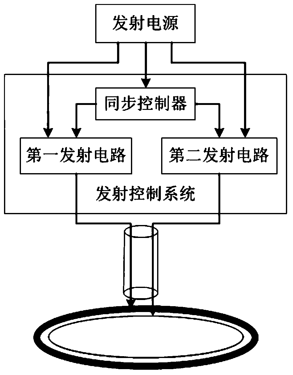
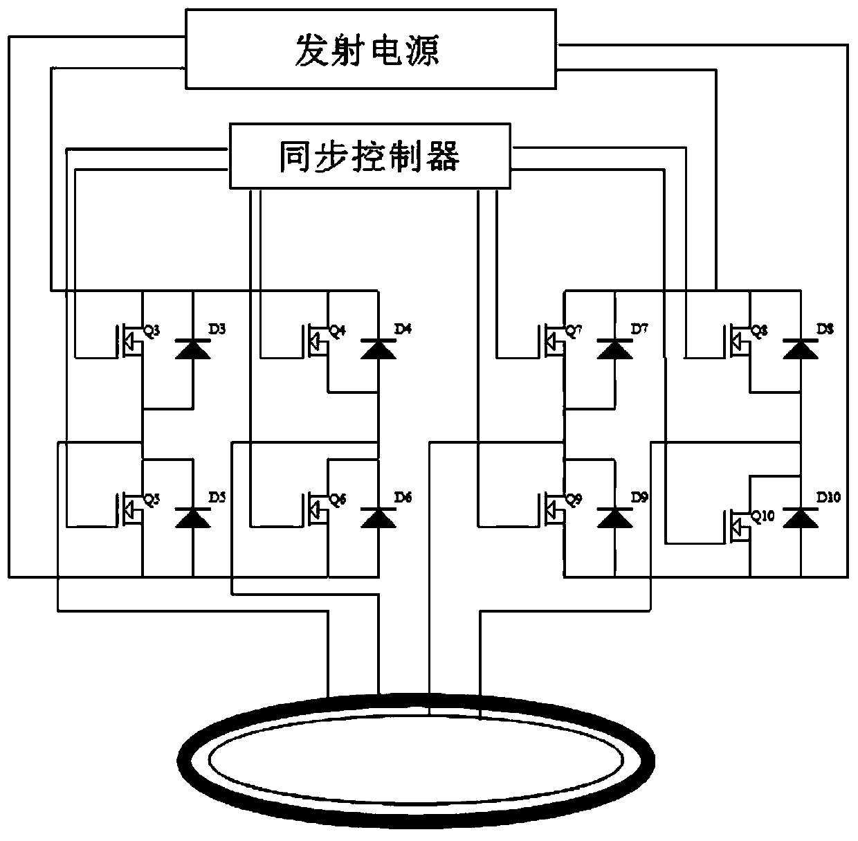
Double-coil coupled multi-wave survey system
A coupled, double-coil technology, applied in the field of transient electromagnetic detection, can solve the problems of not being able to take into account both the shallow detection information and the deep detection information, the power reduction of the power supply system, the loss of the shallow detection information, etc., to improve the shallow detection information. Detection effect, reducing interference, eliminating the effect of multiple magnetic field aliasing
- Summary
- Abstract
- Description
- Claims
- Application Information
AI Technical Summary
Problems solved by technology
Method used
Image
Examples
Embodiment 1
[0083] Parameter settings of the main transmitter coil and the slave transmitter coil:
[0084] Both the main transmitting coil and the secondary transmitting coil adopt single-turn cross-linked polyethylene copper core power cables.
[0085] The main transmitting coil has 4 turns, and the cross-sectional area of the copper core power cable is 80mm 2 , coil radius 17.5m, inductance 3mH, resistance 0.125Ω.
[0086] 1 turn from the transmitting coil, the cross-sectional area of the copper core power cable is 20mm 2 , coil radius 17.5m, inductance 0.26mH, resistance 0.185Ω.
[0087] When emitting a large magnetic moment:
[0088] The transmission is jointly synthesized by the main transmitting coil and the secondary transmitting coil, and the pulse waveform received by the main transmitting coil and the secondary transmitting coil is a bipolar trapezoidal pulse, which rises linearly and falls linearly.
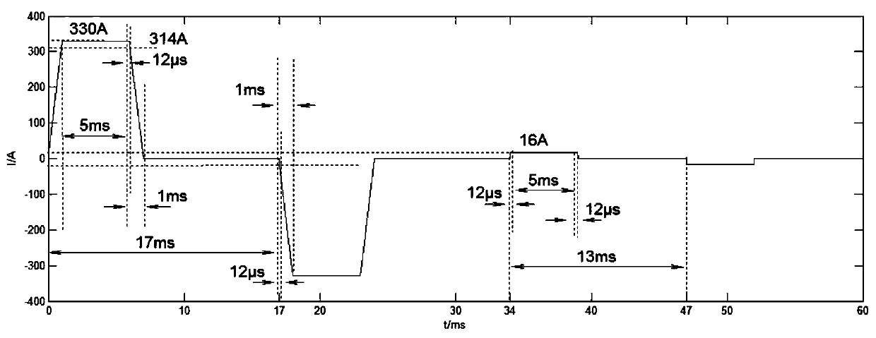
[0089] From image 3 It can be seen that the specific parameters ar...
Embodiment 2
[0107] The parameter settings of the main transmitting coil and the secondary transmitting coil are the same as those in Embodiment 1.
[0108] When emitting a large magnetic moment:
[0109]The emission is jointly synthesized by the main transmitting coil and the secondary transmitting coil, the main transmitting coil passes a bipolar trapezoidal pulse current, and the secondary transmitting coil passes a bipolar triangular wave current. Control the current from the transmitting coil to realize the constant power of the first excitation field, the compensation effect diagram is shown in Figure 5 shown.
[0110] From Figure 4 It can be seen that the specific parameters are:
[0111] Peak magnetic moment: 1300,000Am2, equivalent to 4 turns 330A.
[0112] Flat Top Ripple: 1%.
[0113] Rise time: 1ms.
[0114] Fall time: 1ms.
[0115] Flat top width: 5ms.
[0116] Large magnetic moment half wave: 17ms.
[0117] When emitting a small magnetic moment:
[0118] It is tra...
PUM
 Abstract
Description
Claims
Application Information
 - Generate Ideas
- Intellectual Property
- Life Sciences
- Materials
- Tech Scout
- Unparalleled Data Quality
- Higher Quality Content
- 60% Fewer Hallucinations
Browse by: Latest US Patents, China's latest patents, Technical Efficacy Thesaurus, Application Domain, Technology Topic, Popular Technical Reports.
© 2025 PatSnap. All rights reserved.Legal|Privacy policy|Modern Slavery Act Transparency Statement|Sitemap|About US| Contact US: help@patsnap.com


