Method for operating a moving device

A movement device and movement technology, applied in the direction of transportation and packaging, power control mechanism, wing leaf control mechanism, etc., can solve the problems of increased load on the mechanical structure, adverse effects on the movement comfort of components, abnormal shaking and swinging, etc., to achieve The effect of preventing overload

Active Publication Date: 2017-08-01
AUDI AG
View PDF6 Cites 0 Cited by
  • Summary
  • Abstract
  • Description
  • Claims
  • Application Information

AI Technical Summary

Problems solved by technology

However, in the initial position between the end positions of the member there may be significant wobbling and wobbling or other abnormalities which make the overall movement abnormal
This places an unnecessary load on the mechanics of the drive unit and has a negative effect on the comfort of movement of the components

Method used


Image

  • Method for operating a moving device
  • Method for operating a moving device
  • Method for operating a moving device

Examples


Embodiment Construction

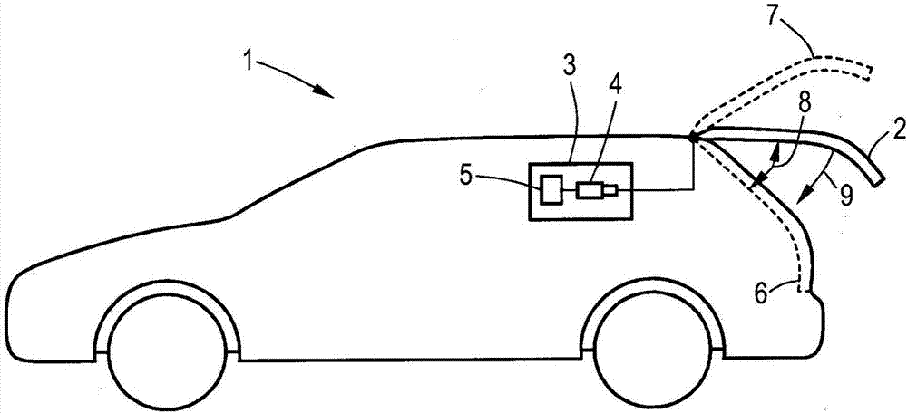
[0018] figure 1 A motor vehicle 1 according to the invention with a rear hood 2 and a movement device 3 with a drive unit 4 , which is controlled by a control unit 5 , is shown in schematic diagram form. Furthermore, the tailgate 2 is shown implicitly in the closed position 6 and in the maximum open position 7 , wherein the shown position of the tailgate 2 is currently the starting position. Positions 6 and 7 are end positions. In addition, the angle of inclination 8 of the rear lid 2 is shown.

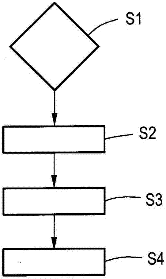
[0019] figure 2 A flow chart of an exemplary embodiment of the method according to the invention is shown. Step S1 here represents the initial state of the method, ie the movement of the rear lid 2 , for example by actuation of an operating element. In step S2, drive parameters are selected on the basis of the current inclination angle 8 representing the starting position and the desired direction of movement 9 . In the present case, this can be achieved, for example, by storing...


PUM


Abstract

Disclosed is a method for operating a moving device (3) for a movable component of a motor vehicle (1), in particular a tailgate (2), said component being movable between two end positions by a drive unit (4) of the moving device (3). In said method, a release energy for the drive unit (4) which is to be used for releasing the component at the beginning of a movement from a starting position is selected in accordance with the starting position.

Description

technical field [0001] The invention relates to a method for operating a kinematic device for a movable component of a motor vehicle, in particular a rear lid, wherein the component can be moved between two end positions by means of a drive unit of the kinematic device between movement. The invention also relates to a motor vehicle comprising a movement device for a movable component and a control unit designed to carry out the method described above, wherein the component can be driven by means of a drive unit of the movement device Movement between two end positions. Background technique [0002] The automatic movement of components between two end positions, in particular an open position and a closed position, is an important comfort feature of modern motor vehicles. Components here are in particular all types of rear hoods, bonnets and doors. For these components it is necessary to use a movement device with a drive unit, which is usually electrically driven or desig...

Claims


Application Information

Patent Timeline
Patent Type & Authority Applications(China)
IPC IPC(8): B60J5/10E05F15/611
CPCE05F15/611B60J5/10E05Y2900/546E05Y2400/60E05Y2400/31E05F15/73B60J5/104
Inventor J·哈特曼P·萨斯曼绍森
Owner AUDI AG
Why Eureka
Try Eureka