Monitoring waveform display method and system

A waveform display and waveform technology, applied in the direction of digital output to display devices, instruments, applications, etc., can solve the problems of inconvenient observation, time break and discontinuity, etc., to achieve the effect of time continuity and improve the convenience of observation

Active Publication Date: 2020-12-22
SHENZHEN COMEN MEDICAL INSTR
View PDF5 Cites 0 Cited by
  • Summary
  • Abstract
  • Description
  • Claims
  • Application Information

AI Technical Summary

Problems solved by technology

The existing monitoring waveform display method mostly adopts the column-by-column scanning method, that is, clearing the historical waveform before drawing the latest waveform at the corresponding position to form a clear scanning zone. As the new waveform continues to move forward, the scanning zone also moves forward. As the dividing line between the latest waveform and the historical waveform, only the latest time value scanned on the time axis will be updated to the current time, and other time values ​​will remain unchanged, so that the time axis is also divided, and the time breaks are not continuous. The traditional monitoring waveform display method Not easy to observe

Method used


Image

  • Monitoring waveform display method and system
  • Monitoring waveform display method and system
  • Monitoring waveform display method and system

Examples


Embodiment Construction

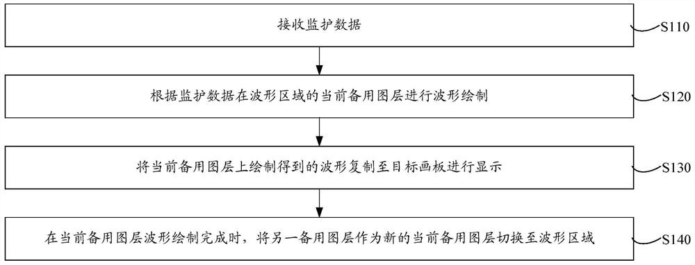
[0019] A monitoring waveform display method is suitable for real-time display of fetal monitoring waveforms. Such as figure 1 As shown, the above method includes the following steps:

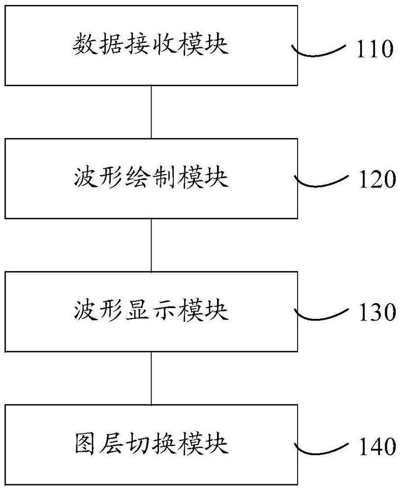
[0020] Step S110: Receive monitoring data. The monitoring data refers to the data obtained by monitoring the patient and can reflect the physiological state of the patient. Specifically, the monitoring data collected by the monitor in real time can be directly obtained.

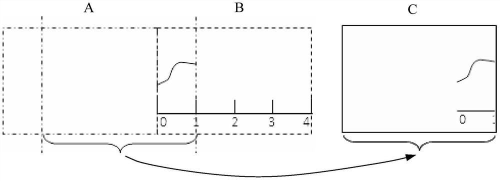
[0021] Step S120: Perform waveform drawing on the current standby layer in the waveform area according to the monitoring data. The waveform area refers to the area where the waveform drawing operation is performed. Multiple backup layers for waveform drawing can be set in advance, and the backup layers are set in the waveform area in a preset order, and after the monitoring data is obtained, the waveform drawing is performed on the current backup layer in the waveform area. Specifically, drawing the waveform can be to draw ...


PUM


Abstract

A monitoring waveform display method. The method comprises: according to received monitoring data, drawing a waveform on a current alternative pattern layer of a waveform area (S120); copying the waveform drawn on the current alternative pattern layer to a target drawing board for display (S130); and when the drawing of the waveform on the current alternative pattern layer is completed, switching another alternative pattern layer to the waveform area (S140). According to the method, the alternative pattern layer can be reused to perform waveform drawing, thereby making the displayed waveforms continuous, and improving the convenience for observation. Further disclosed is a monitoring waveform display system.

Description

technical field [0001] The invention relates to the technical field of waveform display, in particular to a monitor waveform display method and system. Background technique [0002] The monitor is different from the monitoring and diagnostic instrument. It must continuously monitor the patient's physiological parameters for 24 hours, detect the change trend, point out the critical situation, and provide the basis for the doctor's emergency treatment and treatment, so as to minimize the complications and achieve remission and elimination of the disease. Purpose. [0003] In monitoring products, the fetal monitoring waveform is slower than other waveforms, and is closely related to time. When drawing the waveform, it is necessary to attach a time axis. The existing monitoring waveform display method mostly adopts the column-by-column scanning method, that is, clearing the historical waveform before drawing the latest waveform at the corresponding position to form a clear scan...

Claims


Application Information

Patent Timeline
Patent Type & Authority Patents(China)
IPC IPC(8): A61B5/00G06F3/14G06T11/20
CPCA61B5/00A61B5/4362G06F3/1407G06T11/203G06T2210/41
Inventor 李上奖郑远钦
Owner SHENZHEN COMEN MEDICAL INSTR
Why Eureka
Try Eureka