Decoupling axial shim coil design method of magnetic resonance system

A technology of a shim coil and a design method, which is applied in the directions of magnetic resonance measurement, measurement of magnetic variables, measurement devices, etc., can solve the problems of drift of the main magnetic field, affecting the stability of the center field strength, and not considering the electromagnetic coupling of the shim coil and the shim coil. , to achieve the effect of flexibility and safety improvement, high precision

Active Publication Date: 2017-07-28
INST OF ELECTRICAL ENG CHINESE ACAD OF SCI
View PDF6 Cites 16 Cited by
  • Summary
  • Abstract
  • Description
  • Claims
  • Application Information

AI Technical Summary

Problems solved by technology

The above three methods mainly focus on whether the accuracy of the magnetic field generated by the coil meets the design requirements, the amount of wire used is as small as possible, and the self-inductance is as small as possible to design the shim coil, without considering the shim coil and the main Electromagnetic coupling between magnets and shim coils will lead to problems in system stability and system security in the magnet system
The electromagnetic coupling between the shim coil and the main magnet mainly leads to the following problems: (1) When the main magnet is quenched, the current in the main magnet drops rapidly. If the electromagnetic coupling between the shim coil and the main magnet is large, it will be in A large induced current is generated in the shimming coil, which can usually reach hundreds or even thousands of amperes, which makes the shimming coil also quench, and at the same time generates a large amount of heat, causing the coil to be burned; (2) when performing shimming During debugging, the current in the shim coil will be adjusted several times. If the electromagnetic coupling between the shim coil and the main magnet is large, an induced current proportional to the change of the shim current will be generated in the main magnet, causing the main magnet to The magnetic field drifts, affecting the stability of the central field strength
The same electromagnetic coupling between the shim coil and the shim coil will also cause the above problems

Method used


Image

  • Decoupling axial shim coil design method of magnetic resonance system
  • Decoupling axial shim coil design method of magnetic resonance system
  • Decoupling axial shim coil design method of magnetic resonance system

Examples


Embodiment Construction

[0022] The present invention will be further described below in conjunction with the accompanying drawings and specific embodiments.

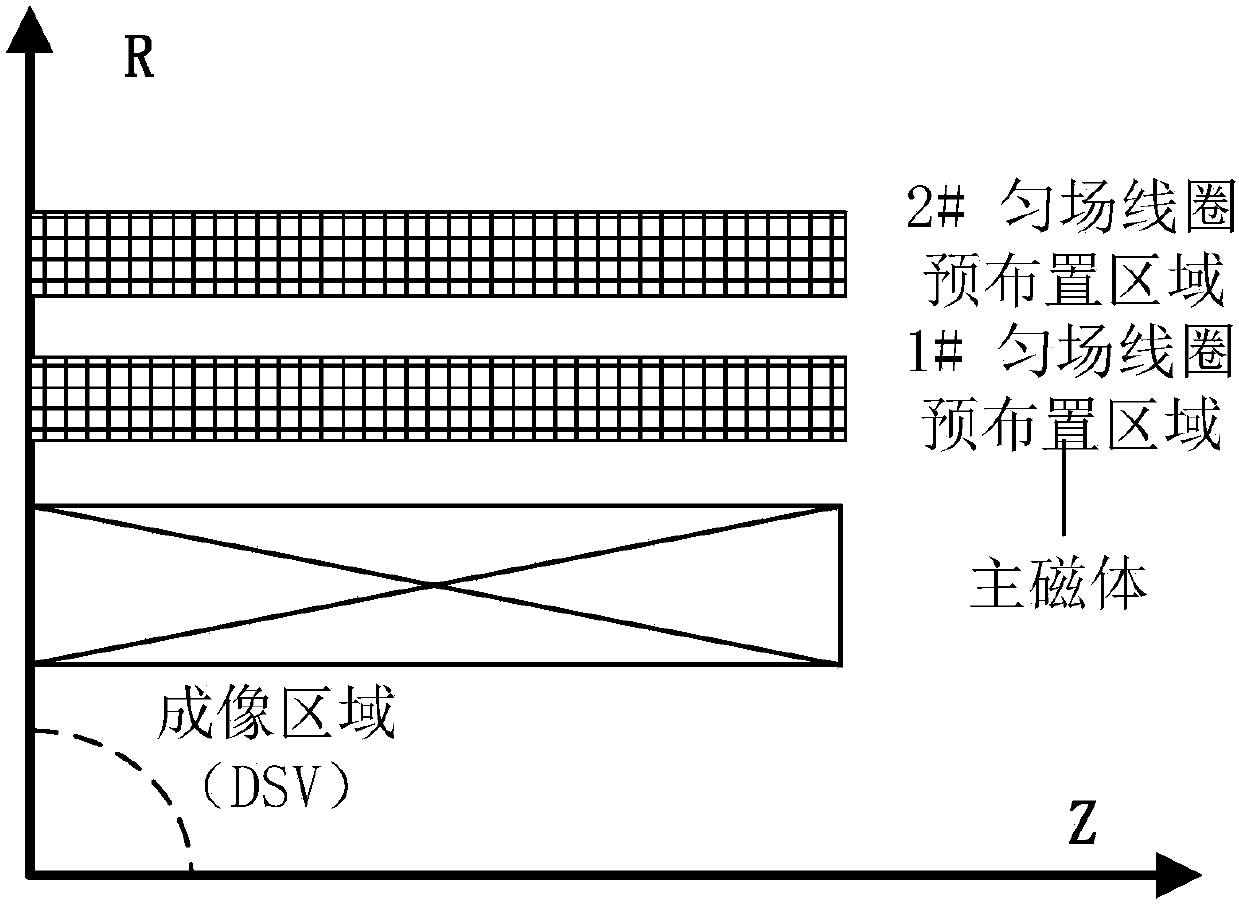
[0023] The embodiment structure of the magnetic resonance magnet system applying the present invention is as follows: figure 2 As shown, the main magnet is located in the innermost layer, and the center is the imaging area with a diameter of 400mm. On the outside of the main magnet, multi-layer shim coils are distributed. In this embodiment, two sets of second-order and fourth-order decoupled axial shim coils are designed simultaneously. At the same time, 100 uniformly distributed points are selected on the surface of the imaging area as the target field points.

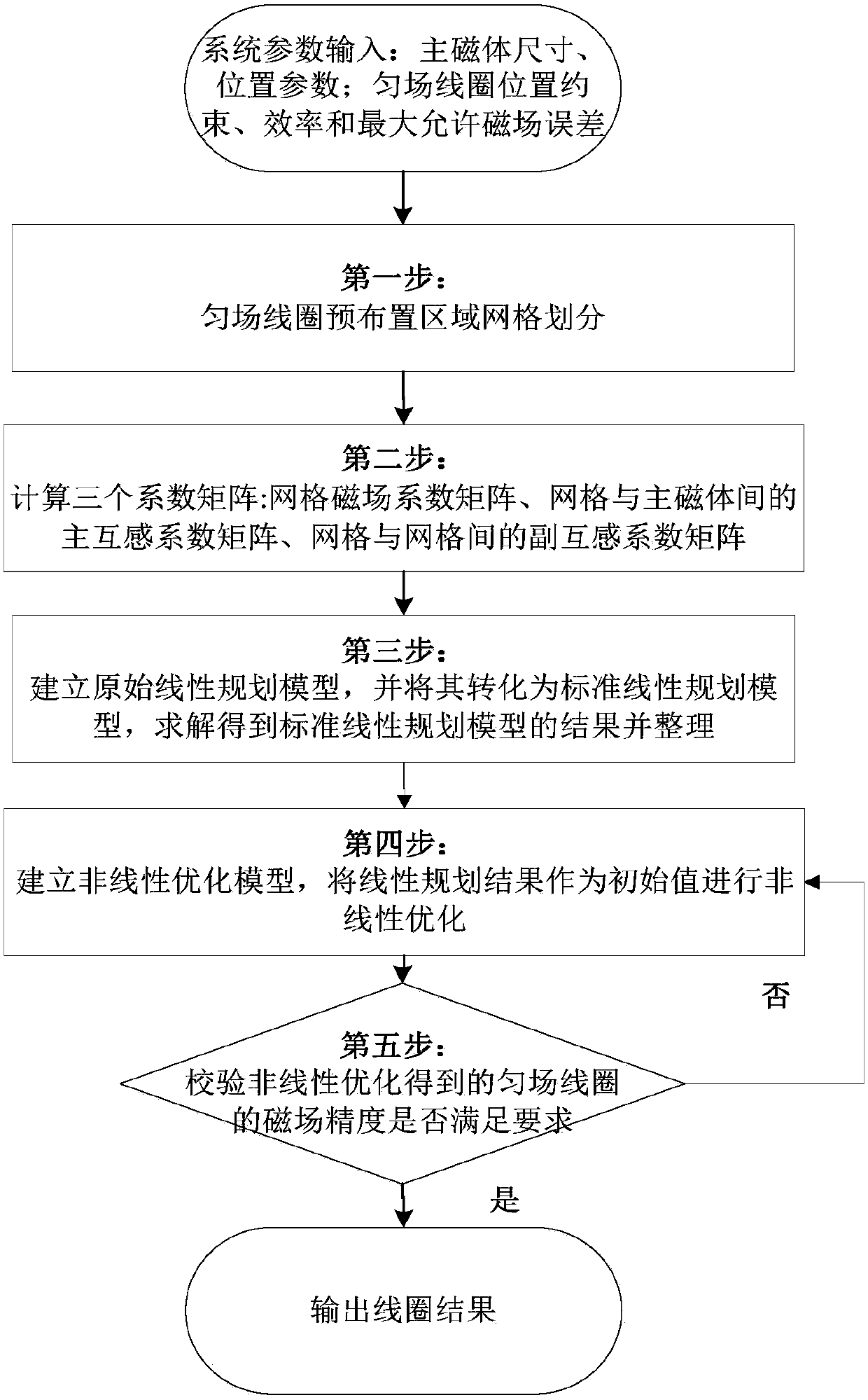
[0024] The steps of the present invention are as figure 1 Shown:

[0025] First import the magnet system parameters required for calculation: the size and spatial position of the main magnet, the spatial coordinates of the target field point, the size limit, efficiency and maximu...


PUM


Abstract

The invention provides a decoupling axial shim coil design method of a magnetic resonance system. The decoupling axial shim coil design method of a magnetic resonance system is integrated with grid dividing, linear programming and nonlinear optimization, and includes the steps: dividing the pre-arranged area of a shim coil into grids with the same size; solving the magnetic field coefficient matrix generated by the grid unit in a target field point; calculating the main mutual inductance coefficient matrix between the grid unit and the main magnet, and at last calculating the auxiliary mutual inductance coefficient matrix among the grid units; in the optimization link, establishing original linear programming of the shim coil, and converting the original linear programming into a standard linear programming model; solving the turns per coil in each grid unit, and arranging the result, and obtaining the optimum shim coil structure with the minimum electromagnetic coupling and the spatial position of each coil; establishing a non-linear programming model of a pre shim coil; taking the spatial position of each coil, obtained through linear programming as the initial solution; and finally solving the final position, of each coil, satisfying the magnetic field error constraint.

Description

technical field [0001] The invention relates to a design method for a decoupling axial shim coil of a magnetic resonance system. Background technique [0002] Magnetic Resonance Imaging (MRI) uses the principle of nuclear magnetic resonance (NMR for short), and according to the difference in energy attenuation in different material structure environments, by applying gradient magnetic fields and radio frequency magnetic fields, the atomic nuclei of the material can be known. position and type, from which to map the structure inside the object. Magnetic resonance imaging has the advantages of no electromagnetic radiation, high image contrast, and tomographic imaging in any direction. It is one of the main imaging methods in the field of medicine and scientific research. [0003] In the magnetic resonance imaging system, the magnet system is mainly responsible for providing a main magnetic field with high field strength, high uniformity and high stability, which is the physic...

Claims


Application Information

Patent Timeline
Patent Type & Authority Applications(China)
IPC IPC(8): G01R33/36G01R33/38
CPCG01R33/3642G01R33/38
Inventor 朱旭晨王秋良李毅
Owner INST OF ELECTRICAL ENG CHINESE ACAD OF SCI
Why Eureka
Try Eureka