A led street light device

A technology for LED street lamps and lamp posts, applied in the field of lighting, can solve the problems of long installation and disassembly, shortening service life, causing accidents, etc., and achieves the effects of improving power supply security, reducing equipment investment, and reducing manufacturing costs.

Active Publication Date: 2018-03-13
XINGHUI LIGHTING ENG GRP
View PDF4 Cites 0 Cited by
  • Summary
  • Abstract
  • Description
  • Claims
  • Application Information

AI Technical Summary

Problems solved by technology

[0002] As a new type of lighting source, LED has many advantages such as long life, high luminous efficiency, multiple light colors, one-time light distribution and directional irradiation, and can work under safe voltage. It has become the development trend of a new generation of light sources and is widely used When it comes to urban road lighting, most of the LED street lamps in the prior art have no protective structure, and maintenance personnel can easily touch the contacts in the lamp holder when replacing the lamp holder or repairing the street lamp, thereby causing electric shock and accidents. Personal and property losses are caused, and the existing LED street lamps generally use tools such as screwdrivers to connect the power supply part and the lighting part together through fasteners such as screws; when LED lighting fixtures fail, it is necessary to use Screwdriver and other tools to disassemble the power supply part and lighting part
Since the installation and disassembly of the power supply department and the lighting department require tools such as screwdrivers, it takes a long time to install and disassemble, and the work efficiency is low. Its own protection is poor, and lightning accidents are prone to occur in thunderstorm seasons, which poses a large safety hazard and reduces the service life

Method used


Image

  • A led street light device
  • A led street light device
  • A led street light device

Examples


Embodiment Construction

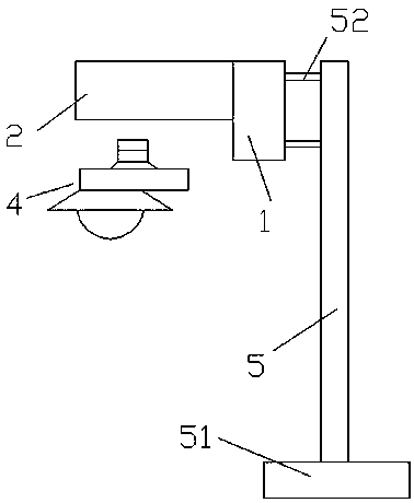
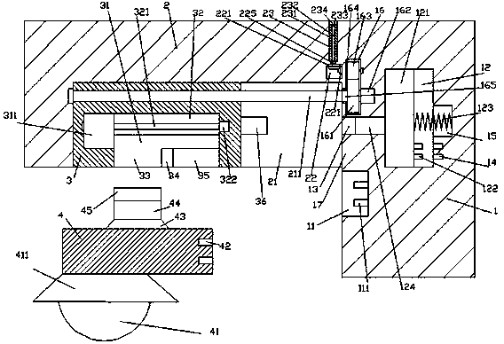
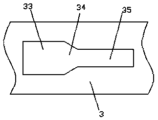
[0026] like Figure 1-Figure 8As shown, an LED street lamp device of the present invention includes a lamp post 5, a body 1, a bracket 2 fixedly arranged on the upper left side of the body 1, and a lamp holder 4. The bottom of the lamp post 5 is fixedly provided with a base 51, and the A straight rod 52 is provided on the upper left side of the lamp post 5, and the end of the straight rod 52 away from the lamp post 5 is fixedly connected with the right end surface of the body 1. Slot 11, the slot 11 is provided with a first latch 111, the bottom end surface of the right side of the bracket 2 is provided with a first sliding groove 21, and the first sliding groove 21 is provided with a locking part 3, The first sliding groove 21 is provided with a first helical rod 211 that is threadedly connected with the locking part 3 and extends to the left and right sides. The body 1 on the right side of the bracket 2 A first sliding connection cavity 12 is provided, a communication groov...


PUM


Abstract

The invention discloses an LED street lamp device. The LED street lamp device comprises a lamp pole, a machine body, a support fixedly arranged above the left portion of the machine body and a lamp cap. A base is fixedly arranged at the bottom of the lamp pole. Straight rods are arranged above the left side of the lamp pole. The ends, deviating from the lamp pole, of the straight rods and the right side end face of the machine body are fixedly connected. An inserting groove is formed in the position, below the support, in the machine body. First plugs are arranged in the inserting groove. A first sliding groove is formed in the bottom end face of the right side of the support. A locking part is arranged in the first sliding groove. A first spiral rod which is in thread fit connection with the locking part and stretches towards the left side and the right side is arranged in the first sliding groove. A first sliding cavity is formed in the position, on the right side of the support, in the machine body. A communicating groove is formed between the first sliding cavity and the first sliding groove. A first empty bin is arranged at the position, above the communicating groove, in the machine body. A second containing cavity is formed in the position, above the right side of the first sliding groove, in the support. A second sliding groove penetrating the top wall of the support is formed in the position, above the second containing cavity, in the support. A pushing rod corresponding to the left side end of the communicating groove is arranged on the right side end face of the locking part. A sliding block is connected in the first sliding cavity in a sliding and matched manner. The LED street lamp device is simple in structure, automatic locking and mounting are achieved, and meanwhile the lightning protection function is achieved.

Description

technical field [0001] The invention relates to the technical field of lighting, in particular to an LED street lamp device. Background technique [0002] As a new type of lighting source, LED has many advantages such as long life, high luminous efficiency, multiple light colors, one-time light distribution and directional irradiation, and can work under safe voltage. It has become the development trend of a new generation of light sources and is widely used. When it comes to urban road lighting, most of the LED street lamps in the prior art have no protective structure. Maintenance personnel can easily touch the contacts in the lamp holder when replacing the lamp holder or repairing the street lamp, thereby causing electric shock and accidents. Personal and property losses are caused, and the existing LED street lamps generally use tools such as screwdrivers to connect the power supply part and the lighting part together through fasteners such as screws; when LED lighting f...

Claims


Application Information

Patent Timeline
Patent Type & Authority Patents(China)
IPC IPC(8): F21S8/08F21V23/06F21V19/00F21V25/00F21W131/103F21Y115/10
CPCF21S8/086F21V19/001F21V23/06F21V25/00F21W2131/103
Inventor 胡广太丁国梅刘翠影傅元桃宋宝良陈勇相静宋有国
Owner XINGHUI LIGHTING ENG GRP
Why Eureka
Try Eureka