Mounting frame

A technology of mounting frame and mounting plate, applied in the direction of machine/bracket, supporting machine, mechanical equipment, etc., can solve the problems of inability to centralize layered installation, non-uniform specifications and dimensions, and achieve simple and convenient installation process, high material strength, Lightweight effect

Inactive Publication Date: 2017-07-28
CHINA NORTH VEHICLE RES INST
View PDF6 Cites 0 Cited by
  • Summary
  • Abstract
  • Description
  • Claims
  • Application Information

AI Technical Summary

Problems solved by technology

[0005] For the design of specific components of vehicles and ships, the equipment models are different, and the specifications and sizes are not uniform, so it is impossible to use the previous pull-out structure for centralized and layered installation

Method used


Image

  • Mounting frame
  • Mounting frame
  • Mounting frame

Examples


Embodiment Construction

[0031] In order to make the purpose, technical solutions and advantages of the embodiments of the present invention more clear, the technical solutions in the embodiments of the present invention are clearly and completely described below in conjunction with the drawings in the embodiments of the present invention. Obviously, the described embodiments are Some embodiments of the present invention, but not all embodiments. Based on the embodiments of the present invention, all other embodiments obtained by persons of ordinary skill in the art without making creative efforts belong to the protection scope of the present invention. The technical solution provided by the present invention will be described in detail below in conjunction with the accompanying drawings.

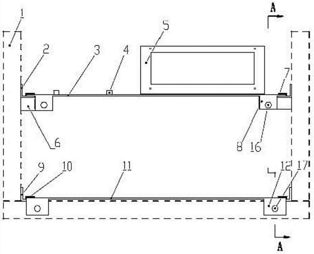
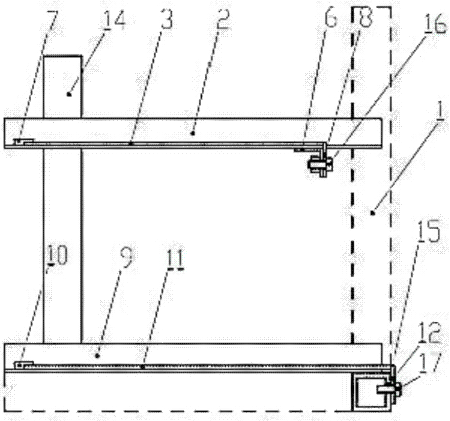
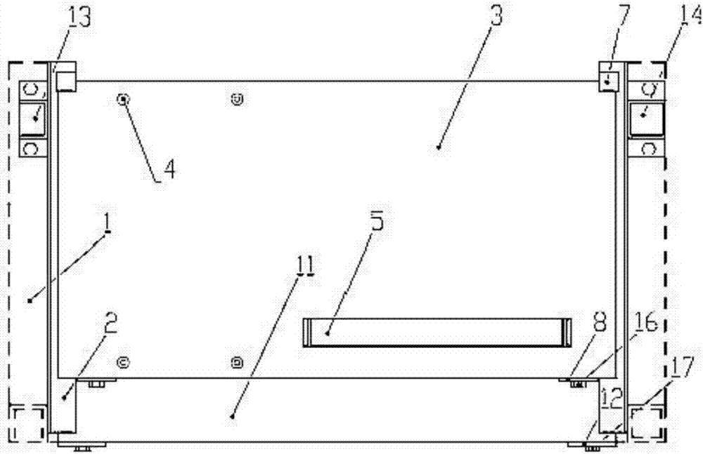
[0032] like Figure 1-4 As shown, it is a mounting frame provided by the present invention. The mounting frame includes two rows of vertical support column assemblies, and the horizontal connecting piece of the re...


PUM


Abstract

The invention provides a mounting frame. The mounting frame comprises two supporting column assemblies arranged vertically, and horizontal connecting parts, wherein the horizontal connecting parts are fixedly connected with the lower ends, close to the supporting column assemblies, of columns in the horizontal direction to form a rectangular horizontal supporting frame; all rows of supporting columns, located on the lower side of the rectangular horizontal supporting frame, of the supporting column assemblies are connected with the horizontal connecting parts correspondingly; outer frames with the height being equal to that of the supporting columns are arranged on the outer sides of all the rows of supporting columns; the connecting parts of the rectangular horizontal supporting frame which are connected vertically in the two rows of supporting columns of the rectangular horizontal supporting frame are provided with pulling type platform sliding rails correspondingly. The mounting frame provided by the invention adopts the mode that a pulling type platform and a mounting attached base are combined, the mounting problem of equipment with different types and dimensions is solved, and the mounting process is simple and convenient.

Description

[0001] Technical field: [0002] The invention relates to installation auxiliary equipment, in particular to a mounting frame. [0003] Background technique: [0004] Any system will have an overall limitation on space, and it is hoped that as much equipment as possible can be arranged within the limited space, so that the convenience of installation and maintenance can be maximized. Therefore, the reasonable layout of the installation space has become the focus and difficulty of the system design. [0005] For the design of specific components of vehicles and ships, the equipment models are different, and the specifications and sizes are not uniform, so it is impossible to continue to use the previous pull-out structure for centralized and layered installation. Therefore, it is necessary to provide a new mounting bracket to adapt to different models and different external dimensions of equipment and to facilitate equipment installation and maintainability to meet the needs of...

Claims


Application Information

Patent Timeline
Patent Type & Authority Applications(China)
IPC IPC(8): F16M11/04F16M11/18
CPCF16M11/04F16M11/18
Inventor 刘启佳庞宝文杨桂玲徐冰黄宗兴王长城米召阳郑凯锋黄冠富左振玉詹瞻羽肖岳峰
Owner CHINA NORTH VEHICLE RES INST
Why Eureka
Try Eureka