
Shock isolation device

A technology of vibration isolation and vibration isolation body, which is applied in the direction of non-rotational vibration suppression, etc., can solve the problems of shortening the life of rubber pads, accelerating aging, and inability to protect electrical equipment, and achieve the effect of extending life and improving reliability

Inactive Publication Date: 2017-07-28
CHINA ELECTRIC POWER RES INST +1
View PDF7 Cites 0 Cited by
  • Summary
  • Abstract
  • Description
  • Claims
  • Application Information

AI Technical Summary

Problems solved by technology

When an earthquake occurs, the horizontal deformation of the rubber isolation pad consumes seismic energy, but when the horizontal displacement exceeds the limit, the isolation device may fail and fail to protect electrical equipment in the subsequent earthquake history
Therefore, the vibration isolation devices currently used in substation equipment generally adopt certain limit measures to limit the range of motion of the vibration isolation support so that it does not exceed the limit horizontal displacement
[0004] Generally, the limiting parts often only limit the displacement of the seismic isolation device in one horizontal direction or in two directions (such as X and Y directions), but the earthquake direction has great randomness, and horizontal earthquakes may occur in all directions of 360°, so Existing limit parts are difficult to meet the requirements of all-directional limit
At the same time, the laminated rubber shock-isolating pad, which is the main functional part of the shock-isolation device, can bear relatively large pressure, but basically cannot bear the tensile force, while the limit parts of the existing shock-isolation device usually only limit the horizontal displacement of the shock-isolation support but cannot limit the isolation force. The vertical displacement of the seismic support, that is, the isolation support cannot be protected from tension
The main electrical equipment may have a tendency to overturn under the action of an earthquake. At this time, the rubber pad of the shock isolation device arranged on the tension side of the bottom of the equipment is easily damaged and fails, which will cause the electrical equipment to lose protection and suffer earthquake damage.
In addition, the limit parts are often arranged on the side of the rubber shock-absorbing bearing in a space, and the two are separated and independent, so that the rubber pad is exposed in the outdoor environment and is easily corroded by rain, dust, oil and other substances, thereby accelerating aging. Shortened rubber pad life

Method used


Image

  • Shock isolation device
  • Shock isolation device
  • Shock isolation device

Examples


Embodiment Construction

[0023] Exemplary embodiments of the present disclosure will be described in more detail below with reference to the accompanying drawings. Although exemplary embodiments of the present disclosure are shown in the drawings, it should be understood that the present disclosure may be embodied in various forms and should not be limited by the embodiments set forth herein. Rather, these embodiments are provided for more thorough understanding of the present disclosure and to fully convey the scope of the present disclosure to those skilled in the art. It should be noted that, in the case of no conflict, the embodiments of the present invention and the features in the embodiments can be combined with each other. The present invention will be described in detail below with reference to the accompanying drawings and examples.

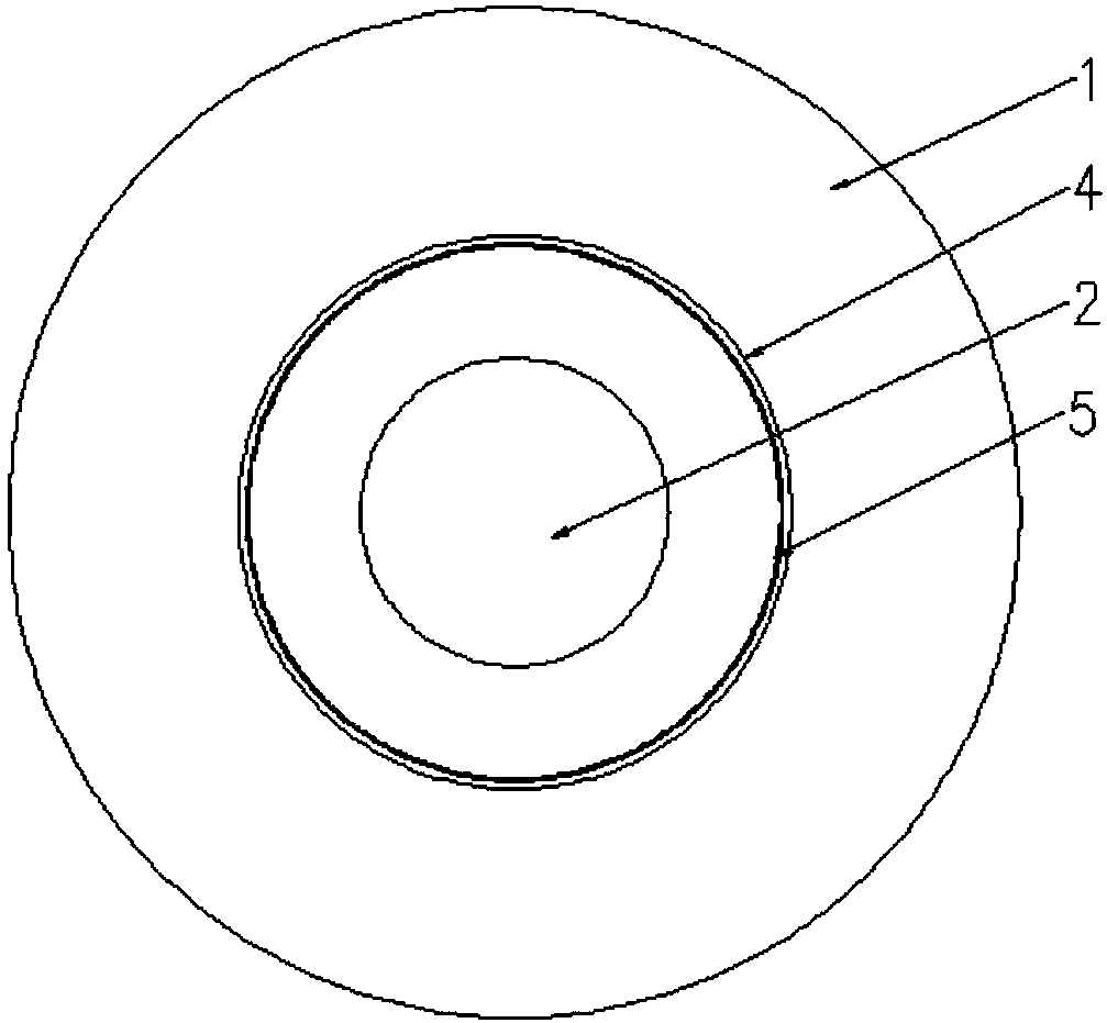
[0024] The shock isolation device of this embodiment adopts a kind of closed position-limiting structure, such as figure 1 As shown, it is mainly composed of...


PUM


Abstract

The invention provides a shock isolation device. The shock isolation device comprises a shock isolation body and a limit mechanism. The shock isolation device is characterized in that the limit mechanism comprises a first limit body and a second limit body; the first limit body is a shell body internally provided with a shock isolation device, and a through hole is formed in the first limit body; the second limit body is embedded in the first limit body and connected with the shock isolation body, and a boss of the second limit body stretches out from the interior of the through hole; and the first limit body limits the displacement of the second limit body.

Description

technical field [0001] The invention relates to the technical field of shock isolation devices for electrical equipment, in particular to a shock isolation device. Background technique [0002] The main box-type electrical main equipment such as the main transformer and high-resistance resistance is relatively heavy. When a strong earthquake occurs, the main electrical equipment may leave its original position, shift or fall off. In addition, the bushing on the equipment box is a weak link that is prone to damage, and the root of the bushing is often broken or damaged under a large earthquake. [0003] Seismic isolation is to separate the ground motion from the structure through some kind of isolation device, so as to achieve the purpose of reducing the vibration of the structure. The seismic isolation device can stably and continuously support the weight of the structure, follow the horizontal deformation of the structure, and have appropriate elastic recovery force. Among...

Claims


Application Information

Patent Timeline
Patent Type & Authority Applications(China)
IPC IPC(8): F16F15/08
CPCF16F15/08
Inventor 林森程永锋卢智成孙宇晗孟宪政张谦高坡刘振林朱祝兵李圣钟珉朱照清王海菠刘海龙
Owner CHINA ELECTRIC POWER RES INST
Learn More