Inductance device with common-mode and differential-mode inductance functions

An inductance device and inductance technology, applied in the field of inductors, can solve the problems of unfavorable space and miniaturization of electronic products, and achieve the effect of good differential mode inductance function, high impedance characteristics, and cost-saving

Inactive Publication Date: 2017-07-25
TECH MOUNT
View PDF5 Cites 1 Cited by
  • Summary
  • Abstract
  • Description
  • Claims
  • Application Information

AI Technical Summary

Problems solved by technology

However, the space occupied by the common-mode inductor and differential-mode inductor of the circuit is not conducive to the miniaturization of electronic products, so it is necessary to propose an inductor device that can eliminate common-mode noise and differential-mode noise and has a smaller volume

Method used


Image

  • Inductance device with common-mode and differential-mode inductance functions
  • Inductance device with common-mode and differential-mode inductance functions
  • Inductance device with common-mode and differential-mode inductance functions

Examples


Embodiment Construction

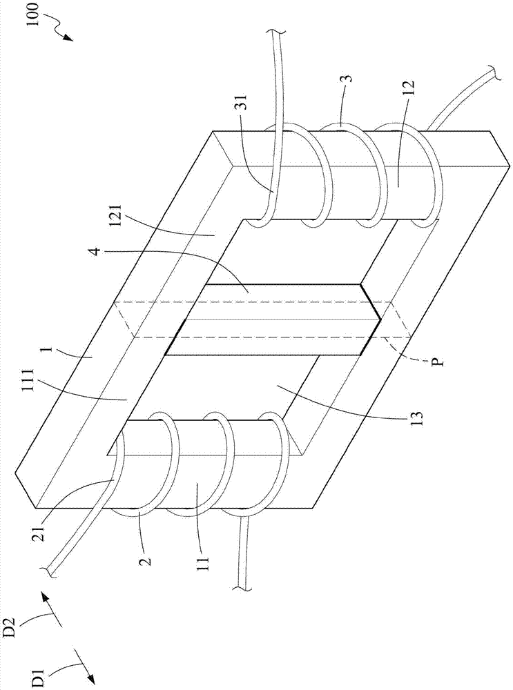
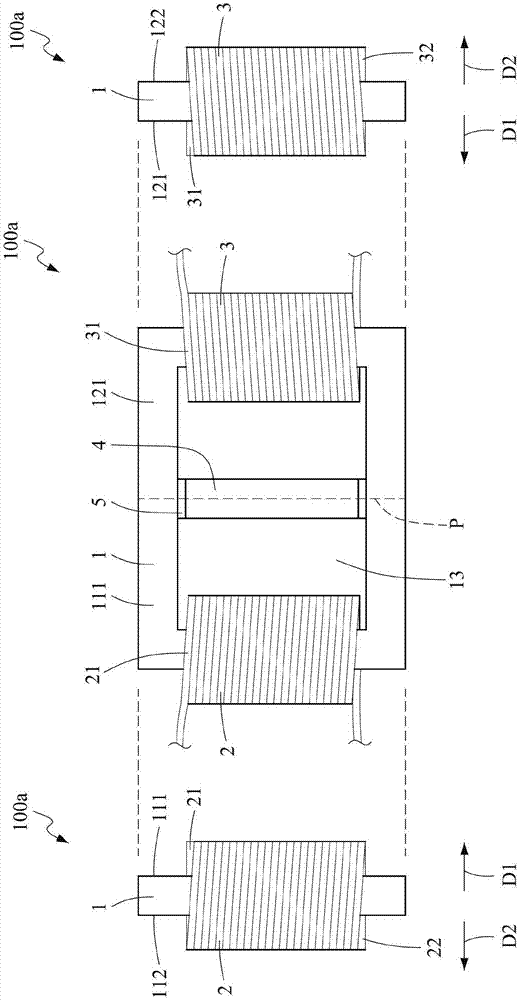
[0053] based on the following Figure 1 to Figure 7c Embodiments of the present invention will be described. This description is not intended to limit the embodiment of the present invention, but is one of examples of the present invention.

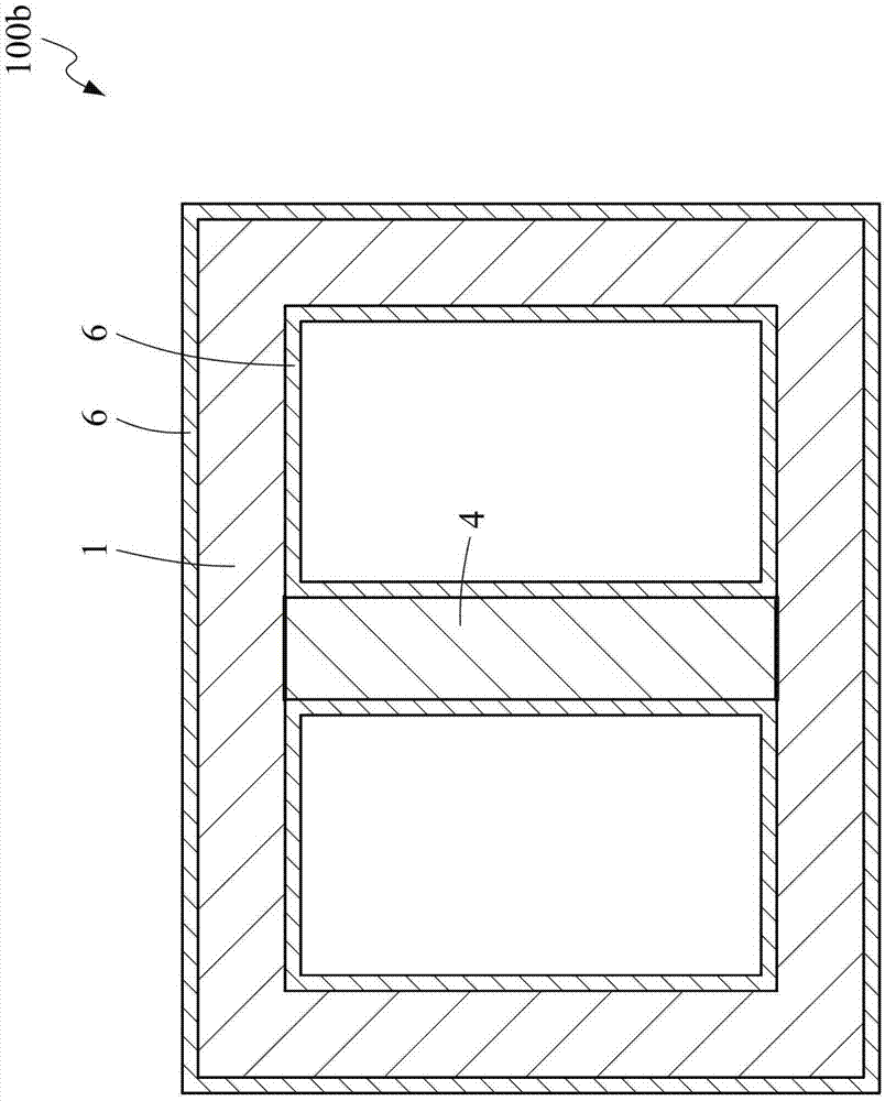
[0054] Such as figure 1 As shown, the inductance device 100 according to the first embodiment of the present invention includes: an inductance frame body 1 having a first winding portion 11, a second winding portion 12 and the first winding portion 11 and the second winding The accommodating area 13 surrounded by the portion 12, the first winding portion 11 and the second winding portion 12 are symmetrically arranged on both sides of the accommodating area 13, the first winding portion 11 has a first winding portion front surface 111 and The first winding part back surface 112, the second winding part 12 has the second winding part front surface 121 and the second winding part back surface 122, the first winding part front surface 111 a...


PUM

PropertyMeasurementUnit
Thicknessaaaaaaaaaa
Widthaaaaaaaaaa

Abstract

An inductance device with a common mode differential mode inductance function, comprising: an inductance frame body with a first winding portion, a second winding portion, and an accommodating area surrounded by the first winding portion and the second winding portion The first coil is wound on the first winding portion; the second coil is reversely wound on the second winding portion, and has a common mode inductance function; The part is joined to the inner edge of the inductor frame to be arranged in the accommodating area, and the magnetic conductive member is spaced between the first coil and the second coil so as to have magnetic induction with the first coil and the second coil respectively, and has a differential mode Inductance function, through the above structure, the inductance device of the present invention has the functions of common mode and differential mode inductors at the same time.

Description

technical field [0001] The invention relates to an inductor, in particular to an inductance device with the function of common-mode and differential-mode inductance. Background technique [0002] With the development of science and technology, electronic products are gradually developing in the direction of miniaturization, which increases the density of components in electronic products and is easily affected by electromagnetic interference (EMI). Generally, inductors are used to filter out EMI. In detail, the conducted EMI circulating in the circuit can be decomposed into two components of common mode noise and differential mode noise. In the prior art, common mode inductors (common mode choke, CMC) are used to eliminate common mode noise, and differential mode Differential mode choke (DMC) eliminates differential mode noise. However, the space occupied by the common-mode inductor and the differential-mode inductor of the circuit is not conducive to the miniaturization of...

Claims


Application Information

Patent Timeline
IPC IPC(8): H01F17/04H01F27/30H01F27/28
CPCH01F17/045H01F27/2871H01F27/306H01F2017/046
Inventor 陈胜有卓景晖黄家平李冠廷
Owner TECH MOUNT
Why Eureka
Try Eureka