A drive mechanism of a linear motor for an elevator

A linear motor and drive mechanism technology, applied in the direction of electric components, electromechanical devices, electrical components, etc., can solve problems such as difficult maintenance, complex structure, and high noise, and achieve the effect of reducing installation procedures, simple assembly structure, and reducing installation costs

Active Publication Date: 2019-02-26
HAIAN COUNTY SHENLING ELECTRICAL APPLIANCE MFG
View PDF8 Cites 0 Cited by
  • Summary
  • Abstract
  • Description
  • Claims
  • Application Information

AI Technical Summary

Problems solved by technology

Due to the high speed and complex speed regulation and position control of the former, it must be equipped with an intermediate reduction transmission device to achieve the purpose of deceleration and turning the rotary motion into a linear motion. Therefore, the structure is complex, maintenance is difficult, and the noise is large.
Although the latter has the characteristics of speed regulation, it still needs an intermediate transmission device that converts rotary motion into linear motion, and also requires a set of DC power supply. Therefore, not only the structure is complicated and the cost is high, but also the maintenance of DC motors is more difficult than that of asynchronous motors. , In addition, there are also hydraulic or pneumatic devices to drive the door. Their drives can be made compact and simple, but the auxiliary equipment (oil pump or air pump and pipeline) is costly, complex in structure, and large in size. The oil pump (air pump) must always be in working condition, so not only the noise is loud, but also the energy consumption is relatively increased. For the above reasons, it is desirable to have a new type of drive element, which not only has the characteristics of simple structure and low noise , and to save energy, the linear motor is an ideal actuator

Method used


Image

  • A drive mechanism of a linear motor for an elevator
  • A drive mechanism of a linear motor for an elevator

Examples


Embodiment Construction

[0029] The present invention will be described in further detail below in conjunction with the accompanying drawings and embodiments. It should be understood that the specific embodiments described here are only used to explain the present invention, not to limit the present invention.

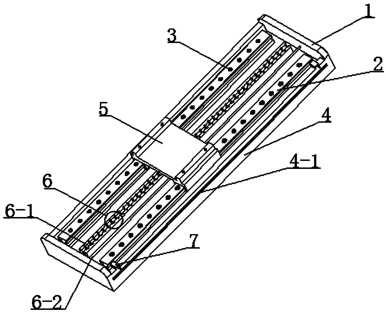
[0030] The present invention discloses a driving mechanism of a linear motor for an elevator, such as figure 1 As shown: the main body is a base 4, the base 4 is U-shaped as a whole, the base includes a stator slot 6, a sliding guide rail 2, a mover seat 5 and a baffle plate 1, and the stator slot 6 is installed in the middle of the base 4 , sliding guide rails 2 are installed on both sides of the stator slot 6, the sliding guide rails 2 on the base 4 and the stator slot 6 are parallel, the sliding guide rails 2 on the base 4 and the stator slot 6 Both are fixed on the U-shaped base 4 with bolts 3, the baffle plate 1 is arranged on the front and rear end surfaces of the U-shaped base 4, the m...


PUM


Abstract

A driving mechanism of a linear motor for an elevator. The body is a base (4); the base (4) is integrally U-shaped and comprises a stator groove (6), slide guide rails (2), a rotor base (5), and baffle plates (1). The stator groove (6) is mounted at the middle position of the base (4). The slide guide rails (2) are respectively provided at two sides of the stator groove (6); the slide guide rails (2) on the base (4) are parallel with the stator groove (6); the slide guide rails (2) on the base (4) and the stator groove (6) are all fixed on the U-shaped base (4) by means of bolts (3); the baffle plates (1) are disposed at the front end surface and the back end surface of the U-shaped base (4); the rotor base (5) is mounted at the middle part of the stator groove (6), and two sides of the rotor base (5) are limited in the grooves of the slide guide rails (2). The driving mechanism uses a simple assembly structure; the installation between a sliding block and the rotor base (5) is eliminated; a rolling wheel (5-6) or other rolling objects are directly installed into in a plane corresponding to the slide guide rail (2) to replace the sliding block, so that the installation costs and installation procedures are reduced.

Description

technical field [0001] The invention relates to the technical field of linear motors, in particular to a driving mechanism of a linear motor for an elevator. Background technique [0002] With the development of society and the rise of tourism, urban facilities are gradually becoming modernized. Hotels, hospitals, subways, scientific research units, workshops, etc. all hope to install doors that can be opened and closed automatically to meet specific needs. [0003] Traditional door operators are generally realized by AC asynchronous motors or DC motors. Due to the high speed and complex speed regulation and position control of the former, it must be equipped with an intermediate reduction transmission device to achieve the purpose of deceleration and turning the rotary motion into a linear motion. Therefore, the structure is complex, difficult to maintain, and the noise is large. Although the latter has the characteristics of speed regulation, it still needs an intermediat...

Claims


Application Information

Patent Timeline
Patent Type & Authority Patents(China)
IPC IPC(8): H02K41/00H02K7/10
CPCH02K7/10H02K41/00
Inventor 范小斌李申孟冬根
Owner HAIAN COUNTY SHENLING ELECTRICAL APPLIANCE MFG
Why Eureka
Try Eureka