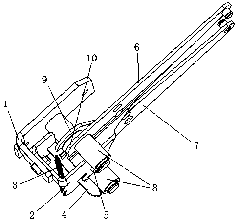
A switchgear and its valve driving mechanism with self-locking function

A technology of driving mechanism and switchgear, which is applied in the direction of pull-out switchgear, switchgear, electrical components, etc., can solve problems such as electric shock safety accidents, and achieve the effect of short moving displacement

Active Publication Date: 2019-06-14
HENAN SENYUAN ELECTRIC CO LTD
View PDF9 Cites 0 Cited by
  • Summary
  • Abstract
  • Description
  • Claims
  • Application Information

AI Technical Summary

Problems solved by technology

But sometimes the maintenance personnel tend to be negligent and forget to manually lock the upper and lower connecting plates, which will lead to electric shock accidents

Method used


Image

  • A switchgear and its valve driving mechanism with self-locking function
  • A switchgear and its valve driving mechanism with self-locking function
  • A switchgear and its valve driving mechanism with self-locking function

Examples


Embodiment 2

[0030]The second embodiment of a switchgear of the present invention differs from the first embodiment in that the end of the deadbolt that cooperates with the unlocking push rod may not be an arc structure, and may also be set as a wedge structure. At this time, the end of the push rod The middle plate is also provided with a matching wedge surface structure.

Embodiment 3

[0031] The third embodiment of a switchgear of the present invention is different from the first embodiment in that the number of spring connection holes on the bolt can also be adjusted according to actual needs, such as one or three.

[0032] The fourth embodiment of a switchgear of the present invention differs from the first embodiment in that the number of connecting plates can also be only one, and at this time there is only one valve and is connected to the connecting plate. At this time, only one The tongue groove is enough.

Embodiment 5

[0033] The fifth embodiment of a switchgear of the present invention is different from the first embodiment in that the pushing part of the middle plate and the pushing part of the side plate can also be formed by correspondingly welded cylinders or round tubes.

[0034] Embodiment 6 of a switch cabinet of the present invention is different from Embodiment 1 in that the structure of the lock tongue is different. The lock tongue includes a push arm and a lock arm, and the length of the push arm is greater than the length of the lock arm. When the unlocking push rod and the push arm push, the locking arm can be driven to separate from the draw-in groove, and at this time, no groove is arranged on the dead bolt.


PUM


Abstract

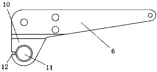
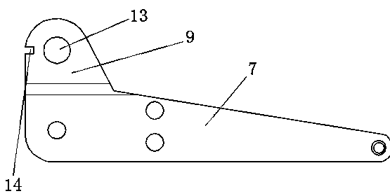
The invention relates to a switch cabinet and a shutter driving mechanism with self-locking function. The shutter driving mechanism comprises a mounting frame and a connecting plate rotatably mounted on the mounting frame. The shutter driving mechanism also includes a guide direction parallel to the rotation axis of the connecting plate. The lock tongue assembled on the mounting frame is moved, and the connecting plate is provided with a lock hole structure. The lock tongue has a locking position that is inserted into the lock hole structure and an unlocking position that is separated from the lock hole structure on its moving stroke. A reset spring is arranged between the mounting brackets, and the lock tongue has a push portion for pushing the corresponding unlocking push rod to move to the unlocking position against the force of the reset spring. During use, the unlocking push rod pushes the lock tongue to make the lock tongue move to the unlocking position along the guide of the mounting frame. At this time, the lock tongue unlocks the connecting plate, and the connecting plate can be rotated to drive the shutter to open, and the unlocking push rod moves in the reverse direction. The shutter is closed, and the lock tongue is guided and moved to the locking position under the action of the return spring. At this time, the connecting plate is locked and cannot be rotated, which plays the role of self-locking of the shutter.

Description

technical field [0001] The invention relates to a switch cabinet and a shutter driving mechanism with self-locking function. Background technique [0002] Among power system products, high-voltage switchgear is one of the important equipment. In the switchgear, the handcart type circuit breaker is the most widely used circuit breaker. The handcart is equipped with moving contacts, and the static contacts are installed in the switchgear and connected to the high-voltage line. Pushing or pulling the handcart To realize the connection or disconnection of the moving contact and the static contact, and then realize the connection or disconnection of the circuit. Since the connection between the static contact and the high-voltage line is a normally live terminal, in order to prevent the maintenance personnel from accidentally touching the static contact when overhauling the circuit and endangering the personal safety of the maintenance personnel, a valve is installed on the fixe...

Claims


Application Information

Patent Timeline
Patent Type & Authority Patents(China)
IPC IPC(8): H02B11/133
CPCH02B11/133
Inventor 刘洋高占魁魏凯尹小岭张燚刚宋浩
Owner HENAN SENYUAN ELECTRIC CO LTD
Why Eureka
Try Eureka