
Automatic air supply device

An air supply device, automatic technology, applied in the direction of adjusting air supply, valve configuration, combustion method, etc., can solve the problems of unsafe, labor-intensive, etc.

Inactive Publication Date: 2017-07-07
山东致远环保设备有限公司
View PDF0 Cites 0 Cited by
  • Summary
  • Abstract
  • Description
  • Claims
  • Application Information

AI Technical Summary

Problems solved by technology

[0002] During the combustion process of the current cremation furnace, when the pressure of the furnace changes, the size of the air supply is manually adjusted, which is not only labor-intensive, but also unsafe

Method used


Image

  • Automatic air supply device
  • Automatic air supply device

Examples


Embodiment Construction

[0011] The present invention will be described in further detail below in conjunction with the accompanying drawings.

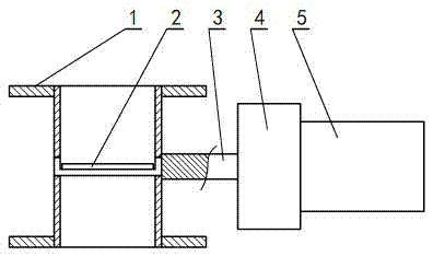
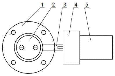
[0012] Flange of the present invention 1 The size of the diameter depends on the size of the diameter of the pipe, in the flange 1 Bolt holes are machined on the top for fixing. Phoenix valve 2 Select standard parts, shaft 3 at work 0-90 Rotate within the range of degrees, used to adjust the size of the air supply, the shaft 3 The two sides are respectively connected to the phoenix valve 2 and reducer 4 , in the reducer 4 The motor is installed on the right side of the 5 , motor 5 Select CNC motor, motor 5 is controlled by the main control system of the furnace PLC controlling. by motor 5 Control reducer 4 , through the reducer 4 control axis 3 , and then through the shaft 3 control phoenix valve 2 , so as to realize the automatic adjustment of the phoenix valve 2 The angle is the purpose of cont...


PUM


Abstract

The invention belongs to an automatic air supply device which is used on a cremator of a funeral parlor. The automatic air supply device is specifically applied to a furnace hearth; a motor is controlled by a master control system PLC of a furnace, so that the master control system PLC of the furnace automatically emits an order to the motor when pressure of the furnace hearth is reduced, the motor controls an air valve, and acts to open the air valve to increase air supply amount to balance pressure of the furnace hearth, and therefore, a required value is reached; otherwise, when pressure of the furnace hearth is increased, the master control system PLC of the furnace automatically emits the order to the power generator which acts to close the air valve to reduce air supply amount to balance pressure of the furnace hearth, and therefore, a required value is reached. An automatic air supply ideal state is realized, and therefore, the automatic air supply device is safe, stable and reliable in work, is convenient to use, saves energy resources, improves efficiency and greatly relieves labor intensity of a worker.

Description

technical field [0001] The invention belongs to an automatic air supply device used on cremation furnaces of funeral parlors, specifically applied in a furnace, and is an automatic air supply device that automatically controls the size of the air supply to the furnace according to the pressure in the furnace. Background technique [0002] In the combustion process of the furnace of the current cremation furnace, when the pressure of the furnace changes, the size of the air supply is manually adjusted, which is not only labor-intensive, but also unsafe. Contents of the invention [0003] The purpose of the present invention is to overcome the above-mentioned shortcomings and provide an automatic air supply device with simple structure and high working efficiency. [0004] The present invention is achieved in this way: an automatic air supply device is composed of a reducer and a motor, and is characterized in that: a motor is installed on the right side of the reduce...

Claims


Application Information

Patent Timeline
Patent Type & Authority Applications(China)
IPC IPC(8): F23G1/00F23L3/00F23N3/00
CPCF23G1/00F23G2900/7009F23L3/00F23N3/002
Inventor 杨开红
Owner 山东致远环保设备有限公司
Learn More