
Waste gas treatment device for industrial furnace

A waste gas treatment device and industrial furnace technology, which is applied in the direction of combination device, liquid separation agent, and dispersed particle separation, etc., can solve the problems of unsatisfactory smoke and dust removal effects of industrial furnaces, achieve ideal smoke and dust removal effects, and increase contact area , good filtering effect

Inactive Publication Date: 2017-07-07
长兴鼎诺机电有限公司
View PDF1 Cites 26 Cited by
  • Summary
  • Abstract
  • Description
  • Claims
  • Application Information

AI Technical Summary

Benefits of technology

This patented technology improves upon existing methods for treating flue gases emitted during manufacturing processes or combustion engines used in industry. It achieves this through adding an improved apparatus called a fluid filter housing system (FAS) containing filters made of solid materials like zinc oxide, activated carbon, silica gel, ceramic material, etc., which removes harmful substances such as nitrogen monoxides, particulate matter, volatile organics, and other chemical compounds found in these sources while also reducing environmental concerns associated therewith. Additionally, it allows for efficient use of space within industrial facilities without causing excessive noise levels due to its compact design. Overall, this innovation provides technical benefits over current ways of removing contaminants from flues generated at various stages throughout their production process.

Problems solved by technology

This patented technology describes different ways to remove harmful substances such as nitrogen oxides (NO) emitted during manufacturing processes like iron making processors' mill cleanings. Existing methods involve exhaust fume disposers which generate significant amounts of wasted flue/fumes due to their high costs associated therewith. Therefore, these technologies have been developed towards reducing NO emission levels without compromising on economics or public safety concerns.

Method used


Image

  • Waste gas treatment device for industrial furnace
  • Waste gas treatment device for industrial furnace
  • Waste gas treatment device for industrial furnace

Examples


Embodiment Construction

[0021] The following will clearly and completely describe the technical solutions in the embodiments of the present invention with reference to the accompanying drawings in the embodiments of the present invention. Obviously, the described embodiments are only some, not all, embodiments of the present invention. Based on the embodiments of the present invention, all other embodiments obtained by persons of ordinary skill in the art without making creative efforts belong to the protection scope of the present invention.

[0022] (In the description of the present invention, it is to be understood that the terms "center", "longitudinal", "transverse", "length", "width", "thickness", "upper", "lower", "front", Orientation indicated by "back", "left", "right", "vertical", "horizontal", "top", "bottom", "inner", "outer", "clockwise", "counterclockwise", etc. Or the positional relationship is based on the orientation or positional relationship shown in the drawings, which is only fo...


PUM


Abstract

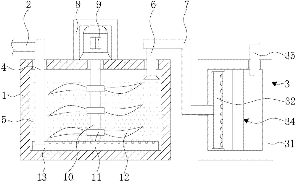
The invention discloses a waste gas treatment device for an industrial furnace. The waste gas treatment device comprises a liquid filter housing, an industrial furnace waste gas pipe and a secondary filter unit. One end of the industrial furnace waste gas pipe is fixedly connected to a gas inlet pipe which is communicated with the industrial furnace waste gas pipe. A filtrate layer is arranged inside the inner chamber of the liquid filter housing. The bottom of the gas inlet pipe successively penetrates through the liquid filter housing and the filtrate layer from top to bottom and extends to the inside of the filtrate layer. One side at the top of the inner wall of the liquid filter housing, far from the gas inlet pipe, is provided with a gas outlet pipe. With the arrangement of the liquid filter housing, the secondary filter unit, the gas inlet pipe, the filtrate layer, the gas outlet pipe and a transmission pipe, the effect of waste gas treatment is achieved. Through a sodium hydroxide solution, sulfur dioxide in waste gas from an industrial furnace is effectively eliminated. The effect of smoke prevention and dust control is ideal, and severe atmospheric pollution caused by waste gas from industrial furnaces is avoided. Therefore, the health of human body is protected, and the device is more environment-friendly.

Description


Claims


Application Information

Patent Timeline
Owner 长兴鼎诺机电有限公司
Learn More