Method Of Operating Switched Reluctance Machine

A technology of switched reluctance motor and switched reluctance drive, which is applied in the direction of single reluctance motor starter, motor control, motor generator test, etc., and can solve the problems of impossible monitoring system insulation, magnetic flux reduction, etc.

Inactive Publication Date: 2017-07-04
NIDEC SR DRIVES
View PDF1 Cites 0 Cited by
  • Summary
  • Abstract
  • Description
  • Claims
  • Application Information

AI Technical Summary

Problems solved by technology

Diodes 23 and 24 then apply the DC voltage from the DC link in opposite directions, causing the magnetic flux (and thus the phase current) in the motor to decrease
Insulation detection systems "see" connections and disconnections to the DC link in chopping and single-pulse modes, which makes it impossible to monitor the insulation of the system

Method used


Image

  • Method Of Operating Switched Reluctance Machine
  • Method Of Operating Switched Reluctance Machine
  • Method Of Operating Switched Reluctance Machine

Examples


Embodiment Construction

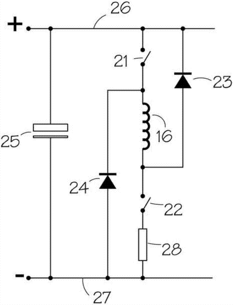
[0031] Figure 5 shows a typical energization scheme for single pulse operation of a switched reluctance motor as described in the Stephenson and Blake paper above. By closing both switches 21, 22, the predetermined rotor angle θ shown in Fig. 5(b) on Apply the DC link voltage. at conduction angle θ c During the application operation continues until the turn-off angle θ off , at the turn-off angle θ off The switch is turned off and the current flows through diodes 23, 24 back to the DC link. During this period of decaying current, energy is returned to the DC link. Although the current in the phase winding is unidirectional, as shown in Fig. 5(b), the current in the DC link is bidirectional. The current continues to decay until the diodes 23, 24 become reverse biased and the current is at θ idle stop. Then there is a period, as shown in Figure 5(b), during which no current flows and the winding is isolated from the DC link.

[0032] Figure 6 shows the corresponding oper...


PUM


Abstract

A controller for a switched reluctance machine is operated to close a switch which would otherwise be open so as to connect a phase winding to the DC link to which the winding is connected during other parts of the electrical cycle. This produces a condition which allows the insulation of the system to be monitored by applying a voltage between the DC link and ground.

Description

technical field [0001] The present invention generally relates to switched reluctance motors and their operation. More particularly, although not exclusively, the invention relates to facilitating the detection of insulation faults in electrical machines. Background technique [0002] The characteristics and operation of switched reluctance systems are well known in the art and are for example presented in "The characteristics, design and application of switched reluctance motors and drives", which is incorporated herein by reference. figure 1 A typical switched reluctance drive is shown in schematic form, where a switched reluctance motor 12 is connected to a load 19 . The DC power source 11 may be a battery or rectified and filtered AC mains or some other form of energy storage. The DC voltage provided by the power supply 11 is switched across a phase winding 16 of the electric machine 12 by a power converter 13 under the control of an electronic control unit 14 . For ...

Claims


Application Information

Patent Timeline
Patent Type & Authority Applications(China)
IPC IPC(8): H02P25/092H02P29/00
CPCH02P29/00H02P25/092H02P29/0241G01R31/12G01R31/34H02P25/08H02P1/163H02P6/16H02P27/06H02P29/024
Inventor M.P.坦卡德P.A.赛克斯I.乔迪森
Owner NIDEC SR DRIVES
Why Eureka
Try Eureka