
New energy automobile charging pile with high safety

A new energy vehicle and safety technology, applied in electric vehicle charging technology, charging stations, electric vehicles, etc., can solve the problems of fire, bulky charging piles, low safety, etc., to improve stability and improve charging safety. Effect

Active Publication Date: 2017-07-04
徐州豪森电气科技有限公司
View PDF6 Cites 69 Cited by
  • Summary
  • Abstract
  • Description
  • Claims
  • Application Information

AI Technical Summary

Problems solved by technology

The input end of the charging pile is connected to the AC power grid, and the output end is equipped with a charging head for charging electric vehicles. The existing charging pile is bulky and occupies a lot of land, which limits its use, low safety, and high cost. Moreover, in the process of charging the electric vehicle by the charging pile, pulling out the charging gun will cause a safety accident, causing casualties, equipment damage and even fire. lock, unlock after charging

Method used


Image

  • New energy automobile charging pile with high safety
  • New energy automobile charging pile with high safety
  • New energy automobile charging pile with high safety

Examples


Embodiment Construction

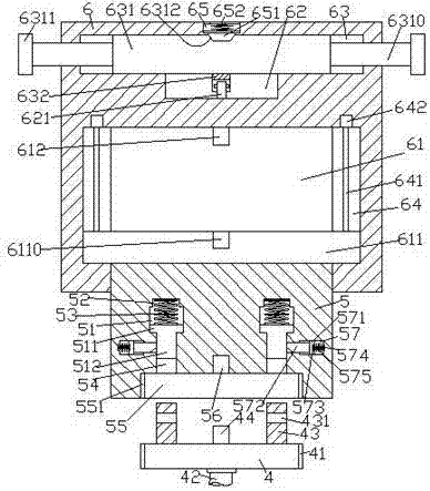
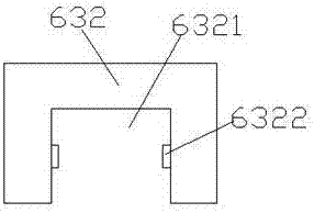
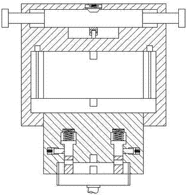
[0022] Such as Figure 1-Figure 8 As shown, a high-safety new energy vehicle charging pile of the present invention includes a body 6 and a charging gun head 4 provided at the bottom of the body 6. The bottom of the body 6 is provided with an accommodation chamber 61, and the accommodation chamber The left and right sides of 61 are provided with sliding grooves 64, and the described sliding grooves 64 are provided with screw rods 641, the top of the described screw rods 641 is connected with the power of the motor 642, and the accommodating cavity 61 is provided with moving beams 611. Both ends of the beam 611 extend into the sliding groove 64 and are threadedly connected with the screw rod 641. The bottom of the moving beam 611 is provided with a connecting block 5, and the bottom of the connecting block 5 passes through the bottom wall of the body 6 and slides Cooperate with the connection, the inside of the connecting block 5 is left and right symmetrically provided with a ...


PUM


Abstract

The invention discloses a new energy automobile charging pile with high safety. The new energy automobile charging pile comprises a machine body and a charging gun head arranged at the bottom of the machine body. A containing cavity is formed in the bottom inside the machine body; sliding grooves are formed in the left and right sides of the containing cavity correspondingly; screws are arranged in the sliding grooves; and the top of the screws are in power connection with motors; a movable beam is arranged in the containing cavity, and the two side ends of the movable beam stretch into the sliding grooves and are connected with the screws in threaded fit mode; a connecting block is arranged at the bottom of the movable beam; the bottom of the connecting block penetrates through the bottom wall of the machine body and is connected with the bottom wall of the machine body in a sliding fit mode; first cavities are formed inside the connecting block in a bilateral symmetry mode; sink grooves are formed in the tops of the first cavities; an embedded groove is formed in the end face of the bottom of the connecting block; communicating holes are formed in the position, between the embedded groove and the first cavities, of the connecting block; second cavities are formed symmetrically in the outer side wall of each communicating hole; first sliding blocks are arranged in the first cavities; first springs are arranged between the tops of the first sliding blocks and the sink grooves; and sliding rods extending into the communicating holes are arranged at the bottoms of the first sliding blocks. The structure is simple, operation is convenient, and automatic locking can be achieved during charging.

Description

technical field [0001] The invention relates to the technical field of new energy vehicle charging, in particular to a new energy vehicle charging pile with high safety. Background technique [0002] As a green transportation tool with broad development prospects, electric vehicles will be popularized at an extremely fast speed, and the future market prospects are also extremely huge. However, electric vehicles need to be charged through charging piles before they can continue to be used. Charging piles are installed in public buildings (public buildings, shopping malls, public parking lots, etc.) and residential parking lots or charging stations, and can charge various types of electric vehicles according to different voltage levels. The input end of the charging pile is connected to the AC power grid, and the output end is equipped with a charging head for charging electric vehicles. The existing charging pile is bulky and occupies a lot of land, which limits its use, low...

Claims


Application Information

Patent Timeline
IPC IPC(8): B60L11/18
CPCB60L53/30B60L53/31Y02T10/70Y02T10/7072Y02T90/12
Inventor 戚祖盛
Owner 徐州豪森电气科技有限公司
Learn More