
Electric shock prevention power supply device in fixed plugging connection

An electric power supply and anti-shock technology, applied in the electric power field, can solve the problems of easy-induced electric shock accidents, failure of normal power supply, limited plugging force, etc., to improve dustproof and waterproof performance, improve stability and safety, and prevent plugging loose connection effect

Active Publication Date: 2017-06-30
JIANGSU XIYI HIGH NEW DISTRICT TECH DEV CO LTD
View PDF5 Cites 58 Cited by
  • Summary
  • Abstract
  • Description
  • Claims
  • Application Information

AI Technical Summary

Problems solved by technology

[0002] The power supply device is an important part of the power equipment. It is mainly composed of a plug part and a socket part and is connected to power supply through plugging. The existing plugging methods are generally manual plugging. Due to manual plugging Instability, when the air humidity is high or the hands are stained with water, it is very easy to induce electric shock accidents, and there is a large safety hazard. External factors such as dragging and pulling make the plug connection loose, resulting in poor contact and failure to work normally with power supply. There are major disadvantages and cannot meet the existing needs.

Method used


Image

  • Electric shock prevention power supply device in fixed plugging connection
  • Electric shock prevention power supply device in fixed plugging connection
  • Electric shock prevention power supply device in fixed plugging connection

Examples


Embodiment Construction

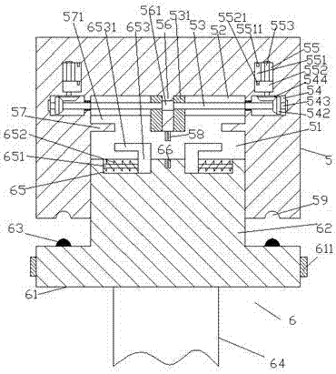
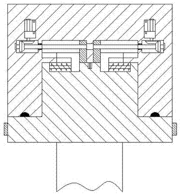
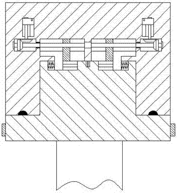
[0021] Such as Figure 1-Figure 4 As shown, a power supply device of the present invention, which is firmly plugged in and prevents electric shock, includes a socket part 5 and a plug part 6. The inner bottom of the socket part 5 is provided with a cavity 51, and the top of the cavity 51 is symmetrical to the left and right. A first sliding groove 52 is provided, and a spacer 56 extending downward is provided between the two first sliding grooves 52, and the extending section of the spacer 56 extends downward into the cavity 51. The socket portion 5 on the side of the first sliding groove 52 facing away from the spacer 56 is provided with a first control chamber 54, and a steering shaft 543 is provided in the first control chamber 54, and each of the first control chambers 54 The sliding grooves 52 are provided with first screw rods 53, the first screw rods 53 are helically connected with push blocks 531, the inner side of the first screw rods 53 is connected with the driving ...


PUM


Abstract

The invention discloses an electric shock prevention power supply device in fixed plugging connection, and the device comprises a socket part and a plug part. The internal bottom of the socket part is provided with an accommodation cavity, and the internal top of the accommodation cavity are provided with first slide grooves which are in left-right symmetry. An isolating block which extends downwards is disposed between the two first slide grooves, and the isolating block extends downwards to enter the accommodation cavity. One side, which departs from the isolating block and is located in the socket part, of each slide groove is provided with a first operation cavity, and the first operation cavity of each first operation cavity is provided with a steering shaft. The interior of each first slide groove is provided with a first spiral rod, and each first spiral rod is in threaded connection with a push block. The inner side of each first spiral rod is connected with a drive motor, and each steering shaft is fixedly provided with a first tooth-shaped wheel, wherein the upper end of the first tooth-shaped wheel is connected with a second tooth-shaped wheel. The interior, at the upper end of each first operation cavity, of the socket part is provided with a second operation cavity, and the inner side of each second operation cavity is provided with a second slide groove.

Description

technical field [0001] The invention relates to the field of electric power technology, in particular to an electric power supply device with firm insertion and electric shock prevention. Background technique [0002] The power supply device is an important part of the power equipment. It is mainly composed of a plug part and a socket part and is connected to power supply through plugging. The existing plugging methods are generally manual plugging. Due to manual plugging Instability, when the air humidity is high or the hands are stained with water, it is very easy to induce electric shock accidents, and there is a large safety hazard. External factors such as dragging and pulling make the plug connection loose, resulting in poor contact and failure to work normally with power supply. There are major disadvantages and cannot meet the existing needs. Contents of the invention [0003] The technical problem to be solved by the present invention is to provide a power supply...

Claims


Application Information

Patent Timeline
IPC IPC(8): H01R24/00H01R13/66H01R13/627H01R13/639H01R13/52H01R13/44
CPCH01R13/44H01R13/5202H01R13/627H01R13/639H01R13/665H01R24/00
Inventor 陆佳浩
Owner JIANGSU XIYI HIGH NEW DISTRICT TECH DEV CO LTD
Learn More