FPGA control method and device during video signal transmitting fault of laser TV set

A video signal and laser TV technology, applied in TV, electrical components, image communication, etc., can solve problems such as display errors, VBO signal processing stability is not very good, etc.

Active Publication Date: 2017-06-20
HISENSE VISUAL TECH CO LTD
View PDF5 Cites 7 Cited by
  • Summary
  • Abstract
  • Description
  • Claims
  • Application Information

AI Technical Summary

Problems solved by technology

[0005] The processing stability of the FPGA to the VBO signal is not very good, somet...

Method used


Image

  • FPGA control method and device during video signal transmitting fault of laser TV set
  • FPGA control method and device during video signal transmitting fault of laser TV set
  • FPGA control method and device during video signal transmitting fault of laser TV set

Examples


Embodiment Construction

[0055] In order to make the object, technical solution and advantages of the present invention clearer, the implementation manner of the present invention will be further described in detail below in conjunction with the accompanying drawings.

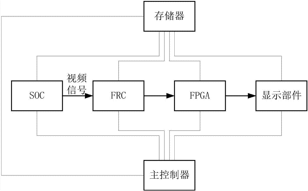
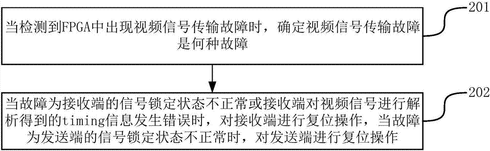
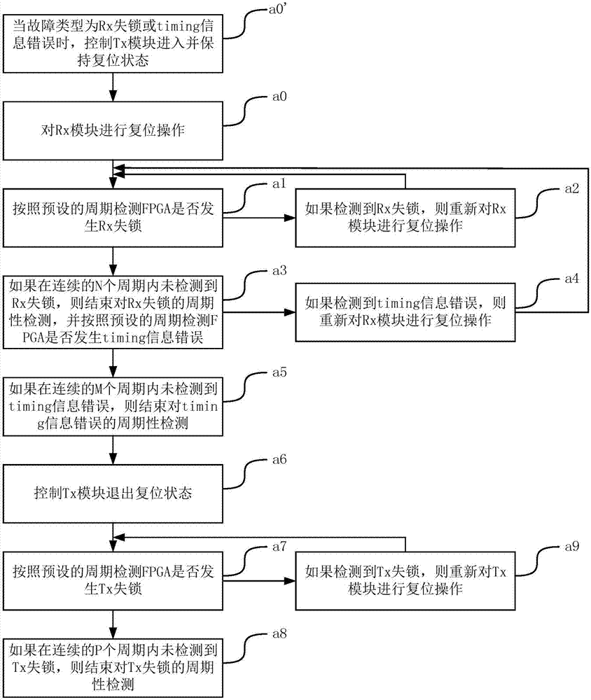
[0056] An embodiment of the present invention provides a method for controlling an FPGA when a laser TV video signal transmission fails, and the method can be implemented by a laser TV. Among them, laser TV can include components such as memory, FPGA, FRC, SOC, display part (DLP), main controller of FPGA, etc. The internal structure diagram of the device can be as follows figure 1shown. The FPGA includes a receiving end, a sending end, and a signal processing module. The receiving end can also be called an Rx (Receiver, receiving) module, and the sending end can also be called a Tx (Transmitter, sending) module. The receiving end and the sending end form a video signal transmission link. The main controller can be used to control the...


PUM


Abstract

The invention discloses an FPGA control method and device during a video signal transmitting fault of a laser TV set, and belongs to the field of video signal processing technologies. The method comprises that when the fault refers to that a signal locking state of a receiving end is abnormal or that timing information obtained by analyzing a video signal in the receiving end has an error, the receiving end is reset; and when the fault refers to that a signal locking state of a sending end is abnormal, the sending end is reset. Thus, the laser TV set is prevented from displaying an error state continuously.

Description

technical field [0001] The invention relates to the technical field of video signal processing, in particular to a method and device for controlling an FPGA when a laser TV video signal transmission fails. Background technique [0002] With the development of technology, laser TV has been widely promoted. In order to meet the requirements of video data transmission speed, the current laser TVs all use VBO (V-By-One, a video signal transmission standard) signal. [0003] During the display process of the laser TV, the VBO signal will pass through SOC (System-On-Chip, system on chip), FRC (Frame Rate Conversion, frame rate converter), FPGA (Field-Programmable Gate Array, field programmable gate array ), DLP (Digital Light Processing, digital light processor) and other components, and then output and display. [0004] In the process of realizing the present invention, the inventor finds that there are at least the following problems in the prior art: [0005] The processing ...

Claims


Application Information

Patent Timeline
IPC IPC(8): H04N17/04
CPCH04N17/04H04N17/045
Inventor 刘西富
Owner HISENSE VISUAL TECH CO LTD
Why Eureka
Try Eureka