
Substation reactive power voltage control method considering dynamic shutting time frame

A voltage control method and substation technology, applied in reactive power compensation, AC network voltage adjustment and other directions, can solve problems such as poor economy and single control method, and achieve the effect of improving safety and economy

Active Publication Date: 2017-06-20
SOUTH CHINA UNIV OF TECH
View PDF3 Cites 2 Cited by
  • Summary
  • Abstract
  • Description
  • Claims
  • Application Information

AI Technical Summary

Problems solved by technology

[0006] The purpose of the present invention is to solve the problem of single control mode and poor economy in the reactive power voltage control process of existing substations, aiming to provide a cooperative control of node voltage and gate reactive power suitable for substations with large fluctuations in voltage / reactive power fluctuations method

Method used


Image

  • Substation reactive power voltage control method considering dynamic shutting time frame
  • Substation reactive power voltage control method considering dynamic shutting time frame
  • Substation reactive power voltage control method considering dynamic shutting time frame

Examples


Embodiment Construction

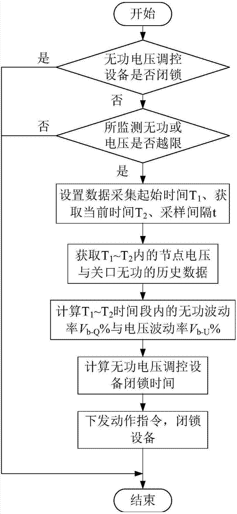
[0036] The specific implementation of the present invention will be further described below in conjunction with the accompanying drawings and examples.

[0037] figure 1 It reflects the specific implementation process of the local reactive voltage control strategy considering the dynamic blocking time. The local reactive voltage control strategy considering the dynamic blocking time includes:

[0038] (1) Set the default AVC strategy, time advance △t, and obtain the number i (i=1...n) of each reactive voltage regulation equipment in the control unit, and the limit value N of the respective number of actions lmt,i , to initialize the blocking time T of each reactive voltage control device lock,i 0, last action time T d,i is the current time, the number of actions N act,i is 0;

[0039] (2) Get the reactive power Q of the current gate t vs. node voltage U t , to determine whether the limit is exceeded; if so, enter step (3); if not, enter step (8);

[0040] (3) Get the c...


PUM


Abstract

The invention provides a substation reactive power voltage control method considering dynamic shutting time frame. The substation reactive power voltage control method is used for solving the problem that an action instruction is frequently issued during wild fluctuation of running quantity of an existing automatic volume control (AVC) strategy. The substation reactive power voltage control method comprises the steps of setting a reference time slot, and acquiring a sampling time interval, a node voltage and a current value and a historical value of a gate reactive power; detecting a shutting state of equipment, and judging whether current reactive power and the voltage exceed a limit or not; respectively calculating the node voltage and a deviation ratio of the gate reactive power within the time slot if the equipment is not locked and the reactive power or the voltage exceeds the limit, thereby obtaining the shutting time frame of reactive power voltage adjustment equipment; and issuing the action instruction according to current running data, and setting the shutting time frame of the equipment. The substation reactive power voltage control method considering the dynamic shutting time frame is proposed by the invention and can be used for controlling the node voltage and the gate reactive power of a substation containing a fluctuation load and accessed with a large amount of distributed power supplies, unnecessary actions of a main transformer shift and a capacitor are reduced, the lifetime of the equipment is prolonged, and the running safety of a power grid is improved.

Description

technical field [0001] The invention relates to the technical field of substation reactive voltage control strategies, in particular to a substation reactive voltage control method considering the setting of dynamic locking time. Background technique [0002] At present, in order to ensure safe, stable, economical and efficient operation of the power grid, the busbar node voltage and gate reactive power of important substations are usually monitored, and the automatic voltage control (AVC) system is used to make the monitored quantities run within a given qualified range Inside. The AVC system uses computer and communication technology to automatically control the reactive voltage regulation equipment in the power grid. The commonly used AVC strategies include the nine-area map strategy, the seventeen-area map strategy, and the twenty-one-area map strategy. It plays a huge role in voltage control, but because it only considers the two-dimensional variables of reactive power...

Claims


Application Information

Patent Timeline
Patent Type & Authority Applications(China)
IPC IPC(8): H02J3/16
CPCH02J3/16Y02E40/30
Inventor 刘轩李峰张勇军
Owner SOUTH CHINA UNIV OF TECH
Learn More