bypass device
A bypass device and mounting hole technology, applied in transportation and packaging, elevators, elevators in buildings, etc., can solve the problems of affecting the life of the device, limited space, difficult to plug and unplug, etc., and achieve accurate and precise plugging and unplugging. , the effect of increasing the guiding effect
- Summary
- Abstract
- Description
- Claims
- Application Information
AI Technical Summary
Problems solved by technology
Method used
Image
Examples
Embodiment 1
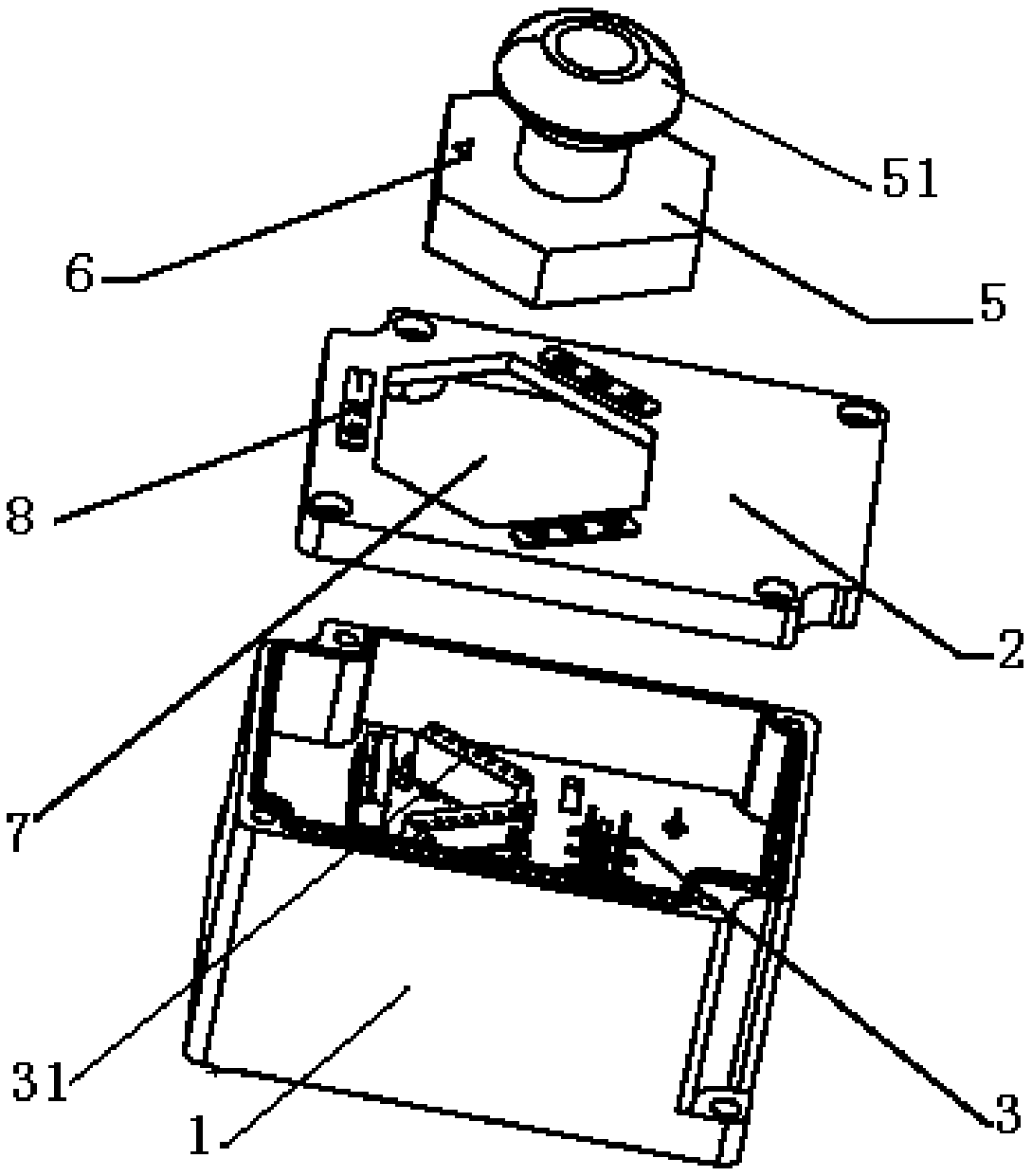
[0062] Such as figure 1 , Figure 4 , Figure 7 As shown, the bypass device includes a box body 1, a front cover 2, and a handle 5;
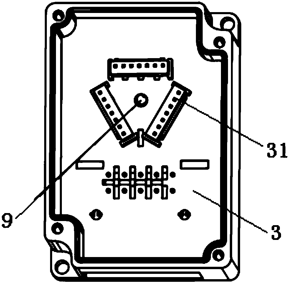
[0063] Such as figure 2 , Figure 5 As shown, the bottom of the box body 1 is fixedly provided with a lower printing plate 3;
[0064] The lower printing plate 3 includes at least one lower insert 31;
[0065] The front cover 2 is buckled and fixed on the box body 1;
[0066] A mounting hole 7 is provided on the front cover 2;
[0067] The top surface of the front cover 2 is provided with one or more position marks 8 at different positions around the installation hole 7;
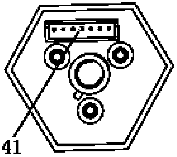
[0068] The circumferential shape of the handle 5 is similar to the shape of the mounting hole 7, and the circumferential dimension of the handle 5 is smaller than the size of the mounting hole 7;
[0069] Such as image 3 , Image 6 As shown, at least one upper insert 41 is fixed on the bottom surface of the handle 5, and a bypass mark 6 is provided on the top surfa...
Embodiment 2
[0078] Based on the bypass device of Embodiment 1, when the upper plug-in 41 on the bottom surface of the handle 5 and the lower plug-in 31 are inserted to the maximum, the top surface of the handle 5 is flush with the top surface of the front cover 2 or is located at the front. In the mounting hole 7 provided on the cover 2.
[0079] In the bypass device of Embodiment 2, when the upper plug-in 41 and the lower plug-in 31 are fully plugged in, the distance from the plug-in position to the front cover 2 should not be too large, because when the plug-ins are combined, the handle 5 is actually the mounting hole 7 of the front cover 2 As a fulcrum, the distance from the insertion position to the front cover 2 is too large, which may easily cause the upper insert 41 to fail to insert the lower insert 31 .
Embodiment 3
[0081] Based on the bypass device in Embodiment 1, when the handle 5 is inserted into the installation hole 7 , the unilateral gap between the handle 5 and the installation hole 7 is between 0.1 mm and 0.5 mm.
[0082] The unilateral gap should not be too small to consider the line tolerance between the printing plate, box body, and upper and lower plug-ins; the unilateral gap should not be too large for the purpose of limiting.
PUM
 Abstract
Description
Claims
Application Information
 - R&D
- Intellectual Property
- Life Sciences
- Materials
- Tech Scout
- Unparalleled Data Quality
- Higher Quality Content
- 60% Fewer Hallucinations
Browse by: Latest US Patents, China's latest patents, Technical Efficacy Thesaurus, Application Domain, Technology Topic, Popular Technical Reports.
© 2025 PatSnap. All rights reserved.Legal|Privacy policy|Modern Slavery Act Transparency Statement|Sitemap|About US| Contact US: help@patsnap.com


