A reducer detector output torque calibrator

A technology of output torque and detector, applied in the direction of force/torque/work measuring instrument calibration/test, instruments, measuring devices, etc., can solve the problems of torque loss, affecting the detection work of the use unit, affecting the accuracy of the indication value, etc. Achieve accurate torque measurement, achieve accuracy traceability, and improve calibration efficiency.

Active Publication Date: 2022-07-26
TIANJIN UNIV
View PDF5 Cites 0 Cited by
  • Summary
  • Abstract
  • Description
  • Claims
  • Application Information

AI Technical Summary

Problems solved by technology

At present, the torque sensors of domestic reducer test devices are all traced to the source of accuracy by submitting for inspection, and only a few domestic verification institutions have the ability to verify the torque value above 5000Nm, which is not only troublesome to disassemble, but also takes too long to verify. To the normal detection work of the user unit, the error of coaxiality caused by disassembly and assembly also affects the accuracy of the indication value
In addition, the torque calibration method of the existing reducer test device is to directly measure the output end of the torque sensor. However, since the torque sensor is often not directly connected to the reducer under test, there is a transmission chain between the torque sensor and the reducer under test. , the calibration state is inconsistent with the use state, because the coaxiality error, deformation, friction and other influencing factors will cause the loss of torque in the transmission, and then cause the actual torque value acting on the reducer (the output torque of the reducer test device) and the torque There is a deviation in the reading value of the sensor, so the output torque of the reducer test device needs to be calibrated to solve the problem that the torque loss in the transmission chain cannot be calibrated and compensated

Method used


Image

  • A reducer detector output torque calibrator
  • A reducer detector output torque calibrator

Examples


Embodiment Construction

[0010] In order to further understand the content of the invention, features and effects of the present invention, the following embodiments are exemplified and described in detail with the accompanying drawings as follows:

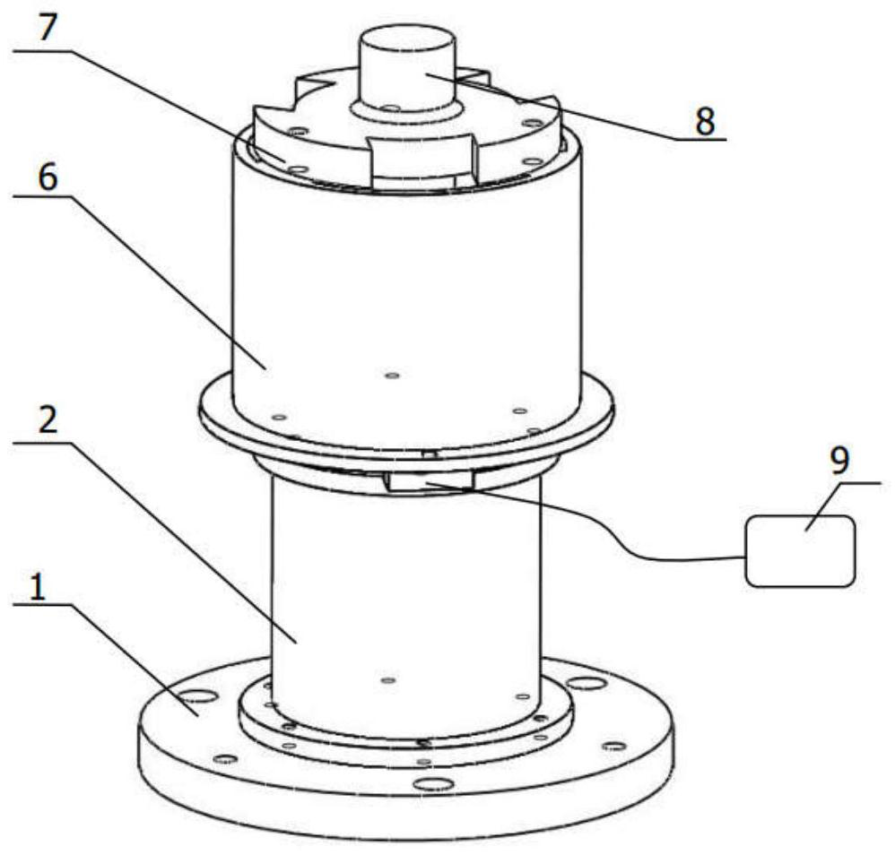
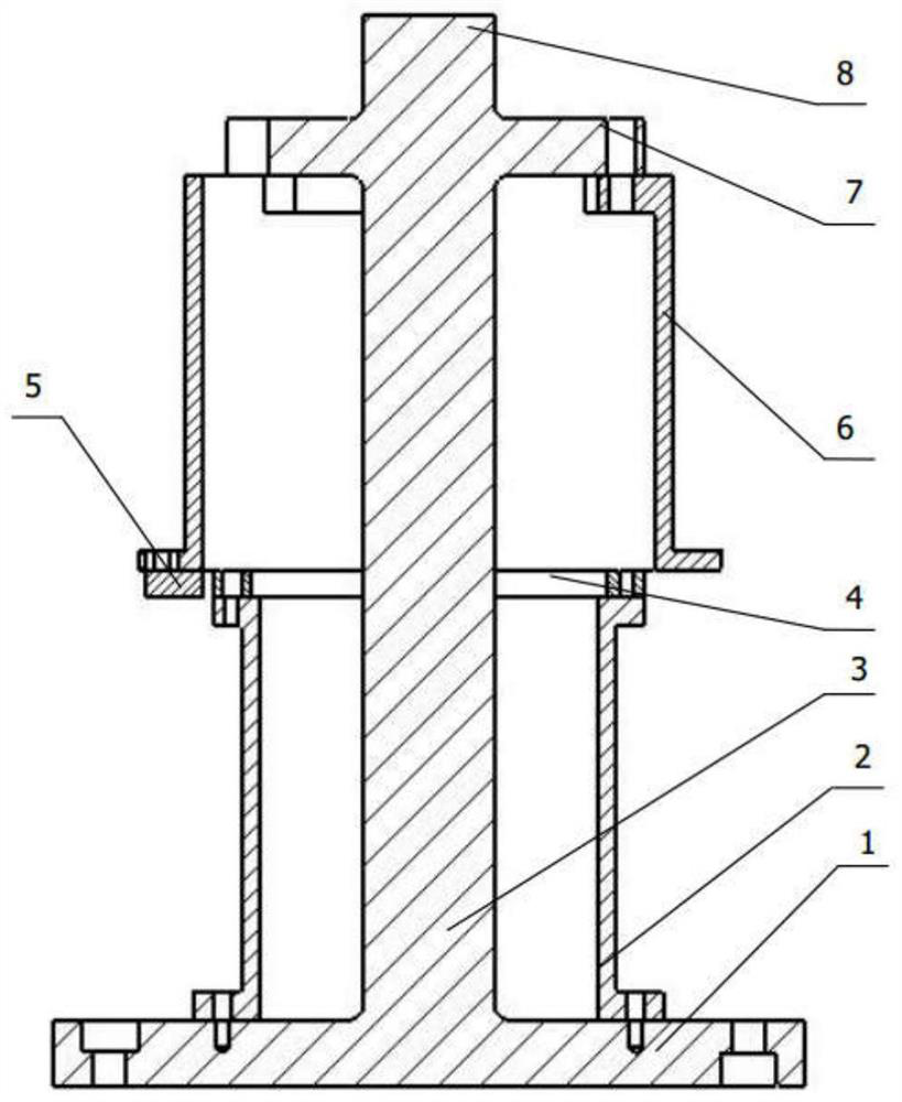
[0011] see figure 1 and figure 2 , a reducer detector output torque calibrator, including a torsion bar 3, the upper end of the torsion bar 3 is a torque input end 8 connected with the output end of the reducer detector, and the lower end is a fixed end, in the torsion bar 3 A mounting frame I6 is fixed on the upper part of the torsion bar 3, a mounting frame II2 is fixed on the lower part of the torsion bar 3, a circular grating ruler 4 is installed on the mounting frame II2, and the circular grating ruler 4 is connected with the torsion bar 3. Coaxially arranged, a reading head 5 adapted to the circular grating ruler 4 is installed on the mounting frame I6 , and the reading head 5 is connected with a data display and recording device 9 .

[0012] In ...


PUM


Abstract

The invention discloses an output torque calibrator of a reducer detector, comprising a torsion bar, the upper end of the torsion bar is a torque input end connected with the output end of the reducer detector, the lower end is a fixed end, and the upper part of the torsion bar is fixedly connected with a torque input end. Mounting frame I, a mounting frame II is fixed on the lower part of the torsion bar, a circular grating ruler is installed on the mounting frame II, the circular grating ruler is coaxially arranged with the torsion bar, and a circular grating ruler is installed on the mounting frame I to match the circular grating ruler. The readhead is connected to the data display and recording device. By using the torsion bar, the invention solves the problem that the traditional measurement method cannot calibrate the torque loss error of the transmission chain between the torque sensor in the reducer measuring device and the measured reducer, and the torsional deformation, friction, coaxiality of the transmission chain, etc. The resulting errors are calibrated together, and the torque sensor of the reducer measuring instrument can be quickly calibrated on site, so that the torque measurement of the reducer measuring instrument is more accurate, and the accuracy can be traced to the source.

Description

technical field [0001] The invention relates to a torque calibrator, in particular to an output torque calibrator of a reducer detector. Background technique [0002] The torque sensor is the core component of the reducer test device, and the torque value measured by it is also an important basic quantity representing the performance of the reducer, so it is very important for the calibration of the torque sensor. At present, the torque sensors of the domestic reducer test devices are all traceable by way of inspection, and only a few domestic verification institutions have the ability to verify the torque value above 5000Nm. To the normal detection work of the unit used, errors such as coaxiality caused by disassembly and assembly also affect the accuracy of the indication. In addition, the torque calibration method of the existing reducer test device is to directly measure the output end of the torque sensor. However, because the torque sensor is often not directly connec...

Claims


Application Information

Patent Timeline
Patent Type & Authority Patents(China)
IPC IPC(8): G01L25/00
CPCG01L25/003
Inventor 裘祖荣王成林李杏华苏智琨胡文川刘佳琛
Owner TIANJIN UNIV
Why Eureka
Try Eureka