Non-shaft-core dual-ball hinge

A double ball and hinge technology, which is applied to hinge plates, door/window accessories, buildings, etc., can solve the problems of shaft core and hinge tube inner wall wear, large resistance, hinge tube wear, etc., to prolong the service life , Small rolling friction and reduced resistance

Inactive Publication Date: 2017-06-09
张武彬
View PDF5 Cites 6 Cited by
  • Summary
  • Abstract
  • Description
  • Claims
  • Application Information

AI Technical Summary

Problems solved by technology

[0002] The traditional hinge includes a door leaf and a door frame leaf. A number of hinge tubes are formed on the sides of the door leaf and the door frame. The door leaf and the door frame are embedded with each other through the hinge tubes. The inner hole is penetrated by a shaft core from top to bottom. , which plays the role of connection and tube alignment. When the hinge installs the door leaf on the door frame, the weight of the door leaf will directly act on the entire connecting axis through the hinge tube of the door leaf, so that the entire connecting axis is tensioned. The inner wall of the hinge tube, when the door leaf is opened and closed, the entire shaft core will directly rub against all the hinge tubes, which will easily cause wear on the shaft core and the inner wall of the hinge tube, resulting in deformation or even damage to the hinge. Relying on the direct sliding friction between the hinge tube and the shaft core to realize the rotation of the door leaf, there is a large resistance when the door leaf is opened and closed, and the disadvantage of laborious operation. The direct sliding friction of the hinge tube of the door frame is also very easy to cause wear and damage to the hinge tube

Method used


Image

  • Non-shaft-core dual-ball hinge
  • Non-shaft-core dual-ball hinge
  • Non-shaft-core dual-ball hinge

Examples


Embodiment Construction

[0024] The specific embodiment of the present invention is described in detail below in conjunction with accompanying drawing:

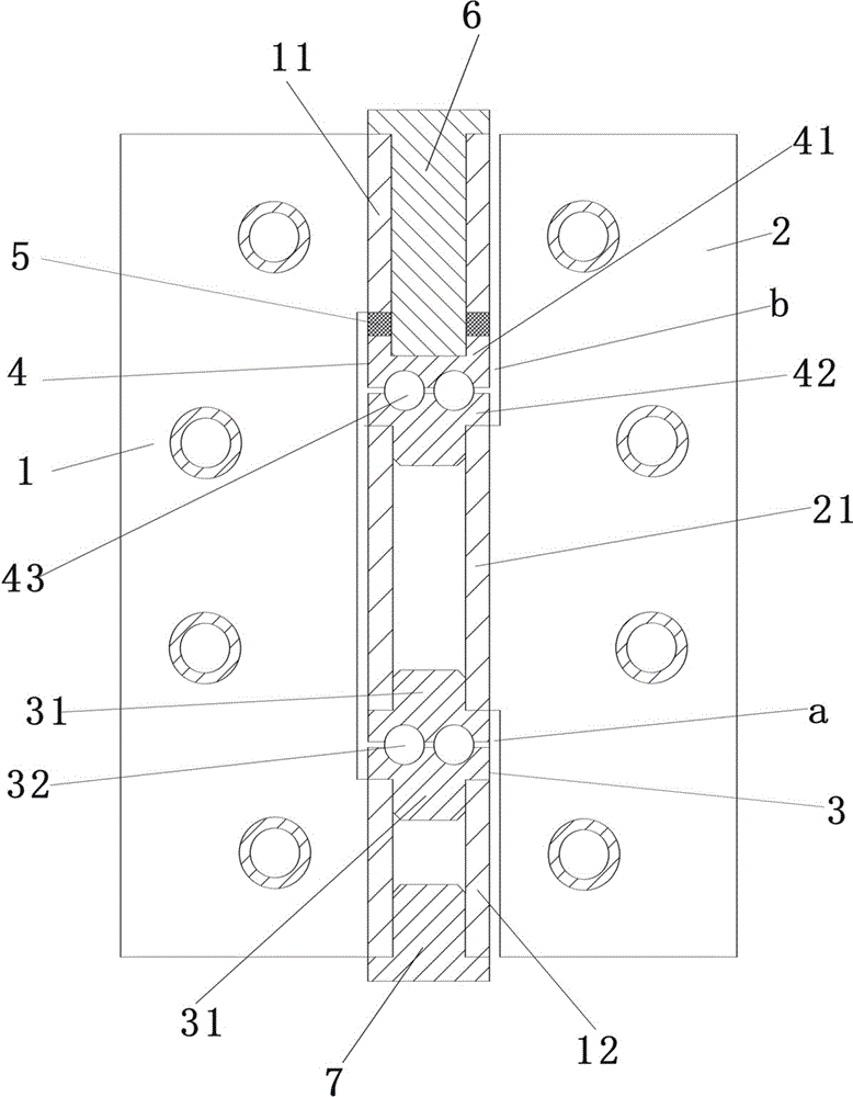
[0025] refer to figure 1 , figure 2 , image 3 and Figure 4 , the non-axis core double ball hinge, including the connecting leaf 1 and the connecting leaf 2, the upper hinge tube 11 and the lower hinge tube 12 are formed on the side of the connecting leaf 1, and the middle hinge tube 21 is formed on the side of the connecting leaf 2 , the middle hinge tube 21 is located between the upper hinge tube 11 and the lower hinge tube 12, and there is a gap between the middle hinge tube 21, the upper hinge tube 11, and the lower hinge tube 12, which is the upper gap b and lower gap a;

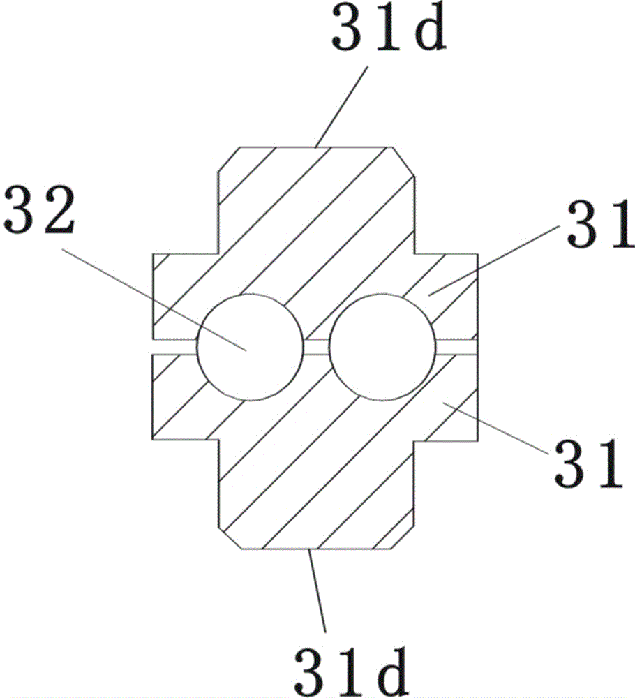
[0026] A lower ball bearing 3 is installed at the lower gap a, the lower ball bearing 3 includes a pair of bead discs 31 and a plurality of balls 32, the bead disc 31 has an annular groove c with a semicircular cross section, and the two bead discs 31 face each other A ...


PUM


Abstract

The invention discloses a non-shaft-core dual-ball hinge. A middle hinge pipe of one connecting sheet of the hinge is located between an upper hinge pipe and a lower hinge pipe of the other connecting sheet, and an upper gap and a lower gap are formed; a lower ball bearing is contained in the lower gap and comprises a pair of ball discs and a plurality of balls, where an annular groove with the semi-circular cross section is formed in each ball disc, the two ball discs are oppositely combined, a channel with the round cross section is formed by the two annular grooves, and a plurality of balls are contained in the channel and are matched with the wall part of the channel; and an upper ball bearing is contained in the upper gap and comprises an upper ball disc, a lower ball disc and a plurality of balls, the upper ball disc and the lower ball disc are each provided an annular groove with the semi-circular cross section, the upper ball disc and the lower ball disc are oppositely combined, a channel with the round cross section is formed by the two annular grooves, the multiple balls are contained in the channel and are matched with the wall part of the channel, the lower ball disc is tightly matched to the middle hinge pipe through steps of the lower ball disc, a blind hole is formed in the top of the upper ball disc, and a connecting pin penetrates the upper hinge pipe and is in tight fit to the interior of the blind hole of the upper ball disc.

Description

technical field [0001] The invention belongs to a hinge for doors and windows, and relates to an improvement of a hinge structure, more specifically, a hinge without a shaft core and bearings. Background technique [0002] The traditional hinge includes a door leaf and a door frame leaf. A number of hinge tubes are formed on the sides of the door leaf and the door frame. The door leaf and the door frame are embedded with each other through the hinge tubes. The inner hole is penetrated by a shaft core from top to bottom. , which plays the role of connection and tube alignment. When the hinge installs the door leaf on the door frame, the weight of the door leaf will directly act on the entire connecting axis through the hinge tube of the door leaf, so that the entire connecting axis is tensioned. The inner wall of the hinge tube, when the door leaf is opened and closed, the entire shaft core will directly rub against all the hinge tubes, which will easily cause wear on the sha...

Claims


Application Information

Patent Timeline
IPC IPC(8): E05D11/04
CPCE05D11/04
Inventor 张武彬
Owner 张武彬
Why Eureka
Try Eureka