Conductive rail connector expansion joint assembly

A technology for expansion joints and connectors, applied in the field of rail transit, can solve the problems of lack of coplanarity, difficulty in meeting the requirements of boundaries and electrical insulation gaps, and discontinuous power reception of trains.

Active Publication Date: 2017-06-09
BYD CO LTD
View PDF5 Cites 8 Cited by
  • Summary
  • Abstract
  • Description
  • Claims
  • Application Information

AI Technical Summary

Problems solved by technology

In order to meet the requirements of current carrying capacity, this type of expansion joint usually has a higher height H for the current connector. When it is used in working conditions such as subway upper and lower contact types that require loose installation margins, this height can meet the margin and electrical insulation. However, when it is used in the working conditions where the side contact type such as straddle monorail has strict requirements on the installation margin, this height is often difficult to meet the requirements of the margin and electrical insulation gap; in addition, this kind of expansion joint is a double-slit three-stage type Expansion joints, when used for side contact installation, the problem of sliding block in the expansion joint is more prominent, the contact surface of the middle slider and the contact surface of the left and right sliders are not in the same plane, when the collector shoe passes through the expansion joint, it will be impacted , resulting in discontinuous train power supply

Method used


Image

  • Conductive rail connector expansion joint assembly
  • Conductive rail connector expansion joint assembly
  • Conductive rail connector expansion joint assembly

Examples


Embodiment Construction

[0054] Embodiments of the present invention are described in detail below, examples of which are shown in the drawings, wherein the same or similar reference numerals designate the same or similar elements or elements having the same or similar functions throughout. The embodiments described below by referring to the figures are exemplary and are intended to explain the present invention and should not be construed as limiting the present invention.

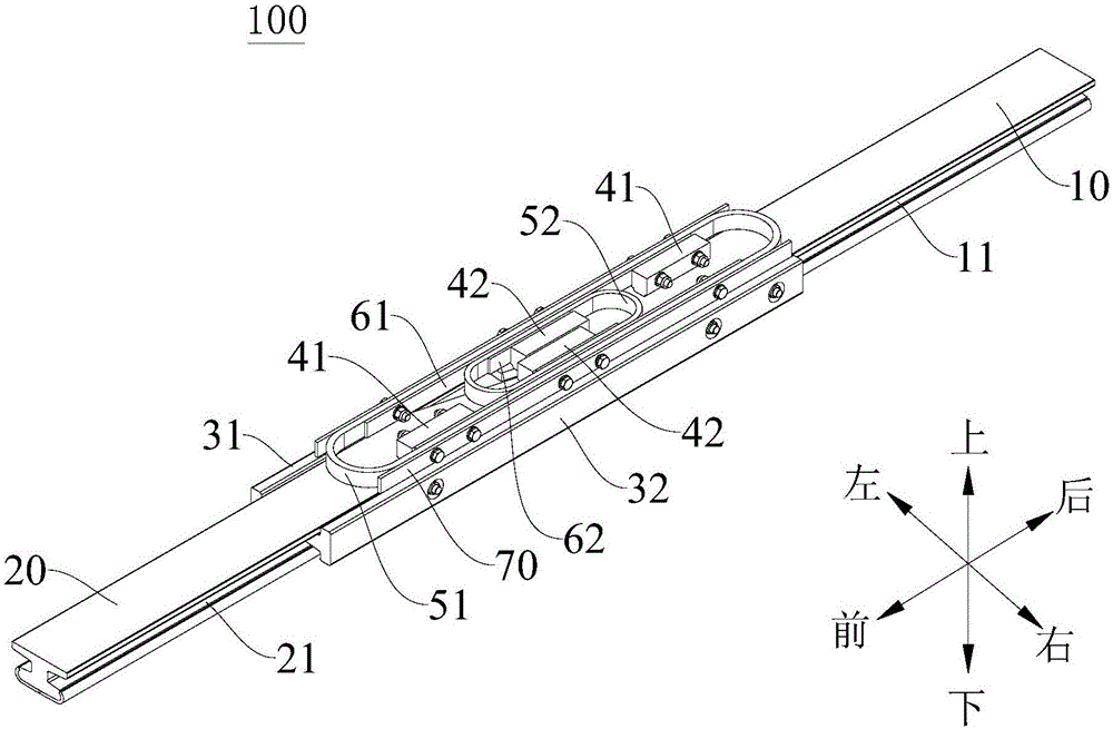
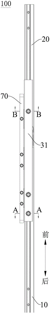
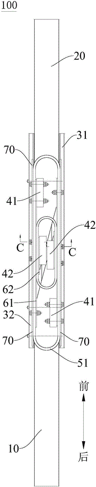
[0055] Attached below Figure 1 to Figure 9 A conductor rail connector expansion joint assembly 100 according to an embodiment of the present invention is described.

[0056] The conductive rail connector expansion joint assembly 100 according to the embodiment of the present invention includes a fixed rail 10 , a moving rail 20 , a first limiting splint 31 , a second limiting splint 32 , an outer ring current connector 51 and an inner ring current connector 52 .

[0057] Specifically, the cross section of the fixed rail 10 is ...


PUM


Abstract

The invention discloses a conductive rail connector expansion joint assembly. The conductive rail connector expansion joint assembly includes a fixed rail, wherein fixed rail grooves are formed in two sides of the fixed rail; a movable rail, wherein movable rail grooves are formed in two sides of the movable rail, and the movable rail and the fixed rail are distributed at an interval in the axial direction; a first limiting clamping plate and a second limiting clamping plate, wherein the first limiting clamping plate and the second limiting clamping plate clamp the fixed rail and the movable rail from two sides and allows the movable rail to move in the axial direction of the movable rail; an outer current connector, wherein the outer current connector forms a long circular structure extending in the axial directions of the fixed rail and the movable rail, and the outer current connector are connected to the fixed rail and the movable rail through connection members; an inner current connector, wherein the inner current connector forms a long circular structure extending in the axial direction of the fixed rail and the movable rail, and the inner current connector is positioned in the outer current connector and is connected to the fixed rail and the movable rail through connection members. The conductive rail connector expansion joint assembly is suitable for a working condition having a high demand for installation bounds and electrical insulating clearances.

Description

technical field [0001] The invention relates to the technical field of rail transit, and more particularly, to an expansion joint assembly of a conductor rail connector. Background technique [0002] The contact rail expansion joint in the related art is composed of a left slider, a middle slider, a right slider, a fishtail splint, a support block, a copper-aluminum transition plate, a thin copper strip, a stainless steel guard plate, a support sleeve and a conductive steel strip. Among them, the left slider, the middle slider and the right slider are three sections made of a contact rail. The left slider and the right slider have horizontal adjustment holes on the rail waist, and the middle slider has a fixing hole on the rail waist. Then use two fishtail splints to clamp the three sliders from both sides, and finally tighten them with bolts. In order to meet the requirements of current carrying capacity, this type of expansion joint usually has a higher height H for the c...

Claims


Application Information

Patent Timeline
Patent Type & Authority Applications(China)
IPC IPC(8): B60M7/00B60M1/30
CPCB60M1/30B60M7/00
Inventor 姚强袁清辉赵文博程冲钟炳辉
Owner BYD CO LTD
Why Eureka
Try Eureka