
Cable lead locking force testing mechanism

A testing mechanism and locking force technology, applied in force/torque/work measuring instruments, measuring devices, instruments, etc., to achieve the effect of convenient use and simple and ingenious mechanism

Pending Publication Date: 2017-06-06
苏州科米隆机电有限公司
View PDF7 Cites 0 Cited by
  • Summary
  • Abstract
  • Description
  • Claims
  • Application Information

AI Technical Summary

Problems solved by technology

However, in the prior art, the finished cable wire produced lacks a device for detecting whether the binding force (or locking force) of the lead head and the cable wire is qualified.

Method used


Image

  • Cable lead locking force testing mechanism
  • Cable lead locking force testing mechanism
  • Cable lead locking force testing mechanism

Examples


Embodiment Construction

[0043] In order to understand the above-mentioned purpose, features and advantages of the present invention more clearly, the present invention will be further described in detail below in conjunction with the accompanying drawings and specific embodiments. It should be understood that these examples are used to illustrate the present invention and not to limit the scope of the present invention. The implementation conditions used in the examples can be further adjusted according to the conditions of specific manufacturers, and the implementation conditions not indicated are usually the conditions in routine experiments. In the following description, many specific details are set forth in order to fully understand the present invention. However, the present invention can also be implemented in other ways different from those described here. Therefore, the protection scope of the present invention is not limited by the specific details disclosed below. EXAMPLE LIMITATIONS.

[...


PUM


Abstract

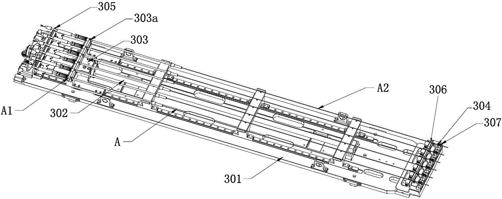
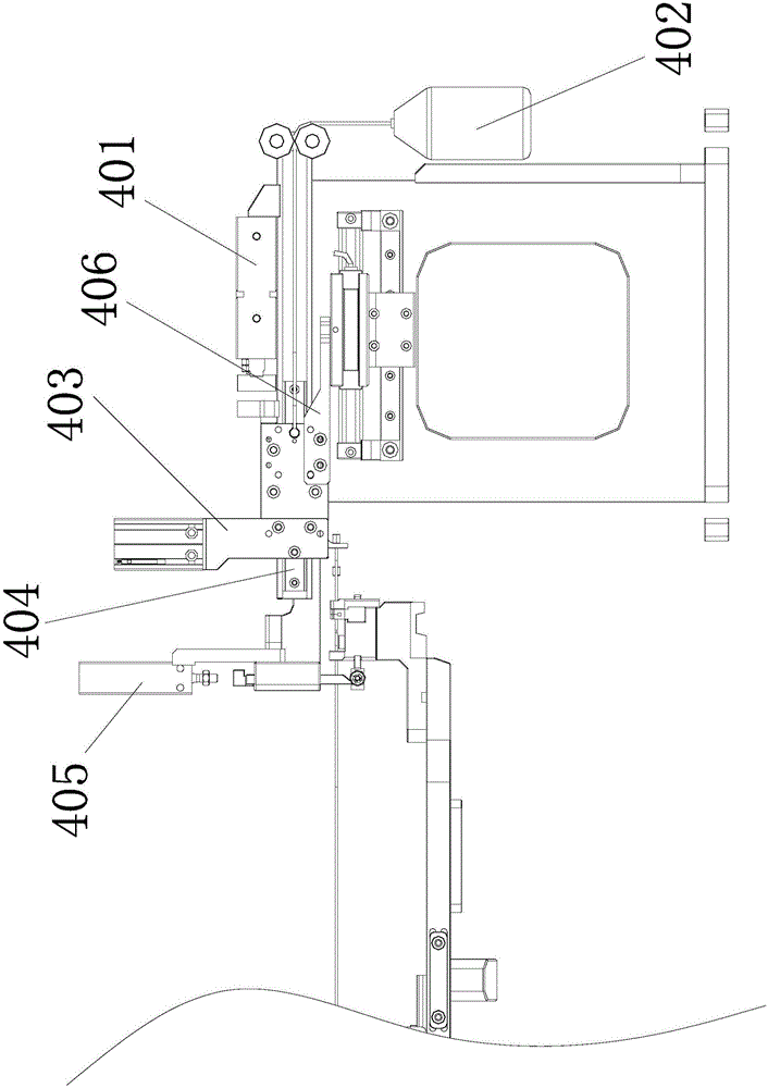
The invention discloses a cable lead locking force testing mechanism. The mechanism comprises: a locking force testing pedestal; a locking force testing pull-back cylinder, which is fixed on the locking force testing pedestal and is provided with a cylinder shaft extending horizontally; a locking force testing clamp cylinder, which is connected with the locking force testing pedestal in a forward and backward sliding manner and which is connected with the cylinder shaft of the locking force testing pull-back cylinder through a tension sensor, the driving end of the locking force testing clamp cylinder being provided with a clamping assembly for clamping / loosening a steel wire portion of a cable A; a locking force testing unlocking cylinder; and a locking force testing locking cylinder. The mechanism is simple and ingenious, is convenient to use, and can quickly and accurately detect whether binding force generated between a lead on a cable finished product and a cable body is qualified.

Description

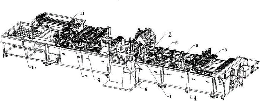
technical field [0001] The invention relates to the field of cable production equipment, in particular to a mechanism for testing the locking force of a lead head of a cable. Background technique [0002] In actual production, it is necessary to make the semi-finished products of the purchased zipper wires into finished zipper wires of certain specifications. The semi-finished zipper wires purchased usually include a steel rope and a casing outside the steel rope. There is a spring between the casing and the steel wire. Both ends of the steel rope go out of the casing, and only one end of the steel rope Set with lead head. [0003] During production, the steel rope of the semi-finished zip line needs to be cut to the required length, and a lead head is also fixedly set (die-cast) at the other end to obtain a standard zip line finished product. However, in the prior art, the finished cable wire produced lacks a device for detecting whether the bonding force (or locking forc...

Claims


Application Information

Patent Timeline
IPC IPC(8): G01L5/00
CPCG01L5/00
Inventor 帅陆军
Owner 苏州科米隆机电有限公司
Learn More