


Quick Research
Generate reliable direction feasibility study reports for your R&D in just a few steps.

Technical Q&A
Discover and master advanced knowledge NOW. Basics, ideas, possibilities, all at once.

Find Solutions
As an expert in R&D theories, this can generate solutions to your technical problems instantly.

Evaluate Feasibility
Analyze your overall solution with one click, know your potential R&D risks in advance.

Monitor Landscape
Get weekly tech updates, stay abreast of the latest tech innovations and key insights.
Heat dissipation unit
A heat dissipation unit and heat dissipation module technology, which is applied in the direction of electrical components, cooling/ventilation/heating transformation, electrical equipment construction parts, etc.
- Summary
- Abstract
- Description
- Claims
- Application Information
AI Technical Summary
Problems solved by technology
Method used
Image


Examples
Embodiment Construction
[0061] The above-mentioned purpose of the present invention and its structural and functional characteristics will be described according to the embodiments of the accompanying drawings.
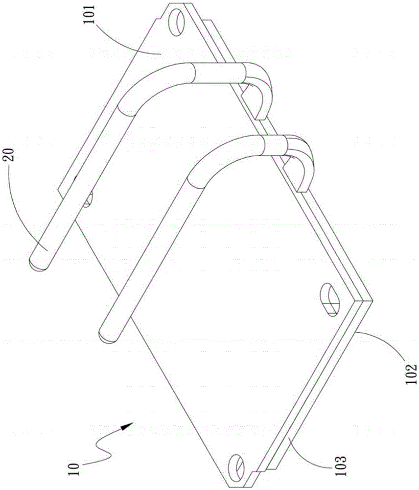
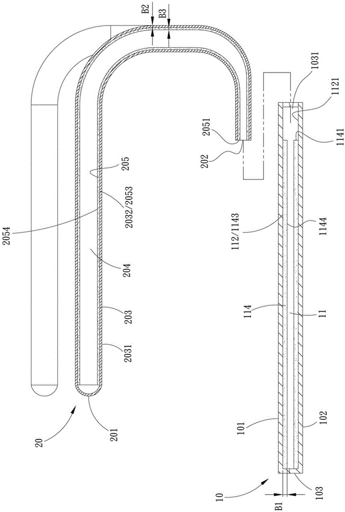
[0062] see figure 1 It is a three-dimensional exploded schematic diagram of the present invention; figure 2 It is a three-dimensional combination schematic diagram of the present invention; image 3 It is a cross-sectional exploded schematic diagram of the present invention; Figure 4 It is a cross-sectional schematic diagram of the present invention; Figure 5 for Figure 4 The local enlarged schematic diagram. As shown in the figure, the present invention includes a casing 10 and at least one heat pipe 20 . The casing 10 is a flat heat conduction unit, such as a vapor chamber or a flat heat pipe, and has a top side 101, a bottom side 102 and a side edge 103 arranged between the top side 101 and the bottom side 102. . The side 103 defines at least one opening 1031 , and the number o...
PUM
 Abstract
Description
Claims
Application Information
 - R&D Engineer
- R&D Manager
- IP Professional
- Industry Leading Data Capabilities
- Powerful AI technology
- Patent DNA Extraction
Browse by: Latest US Patents, China's latest patents, Technical Efficacy Thesaurus, Application Domain, Technology Topic, Popular Technical Reports.
© 2024 PatSnap. All rights reserved.Legal|Privacy policy|Modern Slavery Act Transparency Statement|Sitemap|About US| Contact US: help@patsnap.com