Eureka AIR delivers breakthrough ideas for toughest innovation challenges, trusted by R&D personnel around the world.

A route planning method and device for a terminal control area

A technology for control areas and routes, applied in the field of route planning in terminal control areas, which can solve the problems of fewer departure corridors, longer flight departure time, and increased separation.

Active Publication Date: 2018-07-06
INST OF RADAR & ELECTRONICS CONFRONTATION ARMY AIR FORCE EQUIP RES INST OF PLA
View PDF6 Cites 2 Cited by
  • Summary
  • Abstract
  • Description
  • Claims
  • Application Information

AI Technical Summary

Problems solved by technology

[0005] In the process of realizing the present invention, the inventor found that there are at least the following problems in the related art: the air route allocation method of the terminal control area in the related art makes the available departure corridors of each airport less by pre-allocating different airspaces to each airport, At this time, the routes corresponding to the airspace allocated to other airports are unavailable, so that the interval between consecutive departure flights at a certain airport needs to be increased to ensure the safety of each consecutive departure aircraft, which prolongs the departure time of flights and reduces The number of departure flights within a certain period of time; in addition, when an airport is in the peak period of flight take-off and landing and other airports in the terminal control area are relatively free, the busy airport is not allowed to use the airspace allocated to the idle airport, that is to say , this mode of operation reduces airspace utilization

Method used


Image

  • A route planning method and device for a terminal control area
  • A route planning method and device for a terminal control area
  • A route planning method and device for a terminal control area

Examples


Embodiment Construction

[0092] In order to make the purpose, technical solutions and advantages of the embodiments of the present invention clearer, the technical solutions in the embodiments of the present invention will be clearly and completely described below in conjunction with the drawings in the embodiments of the present invention. Obviously, the described embodiments are only It is a part of embodiments of the present invention, but not all embodiments. The components of the embodiments of the invention generally described and illustrated in the figures herein may be arranged and designed in a variety of different configurations. Accordingly, the following detailed description of the embodiments of the invention provided in the accompanying drawings is not intended to limit the scope of the claimed invention, but merely represents selected embodiments of the invention. Based on the embodiments of the present invention, all other embodiments obtained by those skilled in the art without making...


PUM


Abstract

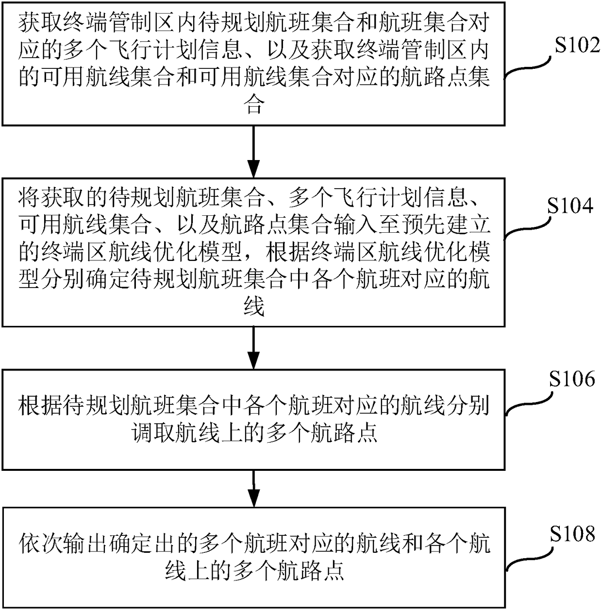
The invention provides an airline planning method and device for a terminal control area. The method comprises steps as follows: multiple pieces of flight plan information corresponding to a to-be-planned flight set and a flight set in the terminal control area are acquired, and an available airline set and a way point set corresponding to the available airline set in the terminal control area are acquired; the information and the sets are input into a pre-established terminal area airline optimization model, and an airline corresponding to each flight is determined according to the terminal area airline optimization model. The terminal area airline optimization model is established in advance, acquired parameters are input into the terminal area airline optimization model, corresponding approach and departure airlines of each flight in the terminal control area are comprehensively analyzed in time and space by use of a target function and multiple constraint conditions, so that the approach and departure airlines are efficiently and accurately planned for each flight, the airspace utilization rate of the terminal control area is increased, and flight delay is reduced.

Description

technical field [0001] The invention relates to the technical field of airspace management and planning in a terminal control area, in particular to a route planning method and device for a terminal control area. Background technique [0002] The rapid and vigorous development of my country's air transport has made the airspace structure more and more complex, and the density of airports has become more and more intensive. In order to alleviate the operational pressure caused by the interaction of multiple airports in busy areas, it is of great significance to optimize and adjust the routes in the terminal control area under the premise of ensuring safety, to maximize the use of airspace resources, meet flight needs, and reduce flight delays. . [0003] Currently, cooperation is required when two or more airports in a TMA are close enough to each other that they can no longer take off and land flights without interfering with each other. To some extent, the flow of air tra...

Claims


Application Information

Patent Timeline
Patent Type & Authority Patents(China)
IPC IPC(8): G08G5/00
CPCG08G5/003G08G5/0043
Inventor 朱永文王长春唐治理陈志杰邵欣朱立彬王家玲
Owner INST OF RADAR & ELECTRONICS CONFRONTATION ARMY AIR FORCE EQUIP RES INST OF PLA
Why Eureka
Eureka Blog
Learn More