10-channel full automatic digital megger

A fully automatic, digital technology, applied in non-electric variable control, measuring devices, instruments, etc., can solve the problems of inaccurate detection and inability to use, and achieve the effect of improving work accuracy, saving processing resources, and efficient processing.

Active Publication Date: 2017-05-31
PINGDINGSHAN POWER SUPPLY ELECTRIC POWER OF HENAN
View PDF8 Cites 1 Cited by
  • Summary
  • Abstract
  • Description
  • Claims
  • Application Information

AI Technical Summary

Problems solved by technology

The fault detection method proposed by the present invention is simple, convenient and easy to operate. The multimeter is clamped in the detection device, which is easy to maintain and replace. The automatic comparison of phase voltage data is realized through the control center, and the detection value and fault detection result can be displayed in real time; although it is public The detection method of the transformer is improved, but it still needs to use a digital multimeter, which still has inaccurate detection and cannot be used in harsh environments. Therefore, a fully automatic digital shaker capable of temperature and humidity adjustment is needed.

Method used


Image

  • 10-channel full automatic digital megger
  • 10-channel full automatic digital megger
  • 10-channel full automatic digital megger

Examples


Embodiment 1

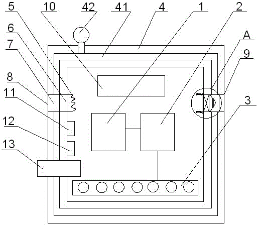
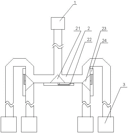
[0038] The 10-way fully automatic digital meter includes a housing 4, a signal processing module 1 arranged in the housing 4, a signal acquisition unit 3 arranged outside the housing 4, and a signal processing module 1 arranged between the signal processing module 1 and the A signal distributor 2 between the signal acquisition units 3;

[0039] The signal acquisition unit 3 includes a terminal and a signal conversion module arranged at the rear of the terminal, and the signal conversion module is connected to the signal distributor 2;

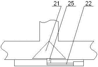
[0040] The converter 2 includes a main T-type conversion module, auxiliary T-type conversion modules arranged on both sides of the main T-type conversion module, and a main steering block arranged in the main T-type conversion module and the auxiliary T-type conversion module 21 and the auxiliary steering block 23, and the main telescopic link 22 and the auxiliary telescopic link 24 that control the main steering block 21 and the auxiliary stee...

Embodiment 2

[0049] S1: Connect the signal acquisition unit of the device with the transformer insulation section to be tested, then transmit the signal source to the signal distributor, and gather the signals to the signal processing module through the signal distributor for signal processing;

[0050] S2: When multiple insulation segments are required to be detected simultaneously, the signal distributor is used to adjust and transmit all the signals to the processor. Since the pulse frequency of the emitted optical signal is different, it can be accurately processed by the CUP analyze it;

[0051] S3: When the humidity sensor or temperature sensor detects that the temperature and humidity inside the device exceed the optimum operating environment, start dehumidification or temperature adjustment, and for dehumidification, turn on the fan to make the fan blow the umbrella, and the umbrella will be linked Pull the air-out waterproof and breathable membrane to keep it away from the fan, so...

Embodiment 3

[0056] Both the main telescopic rod 23 and the secondary telescopic rod 24 are electric telescopic rods.


PUM


Abstract

The invention discloses a 10-channel full automatic digital megger. The 10-channel full automatic digital megger comprises a casing body, a signal processing module arranged in the casing body, a signal acquisition unit arranged outside the casing body, and a signal distribution device which is arranged between the signal processing module and the signal acquisition unit. According to the invention, a signal passes through a converter; a humidity adjustment module and a temperature adjustment module are arranged in the casing body to adjust the temperature and humidity of the digital megger to ensure that the device is in the best working condition at all times; and the 10-channel full automatic digital megger is worthy of application and promotion.

Description

technical field [0001] The invention relates to the technical field of power transformation operation and maintenance equipment, in particular to a 10-channel fully automatic digital shaker meter. Background technique [0002] The digital shaking meter is composed of medium and large scale integrated circuits. This meter has large output power, high short-circuit current value, and multiple output voltage levels. The working principle is that the DC high voltage generated by the internal battery as the power supply through DC / DC conversion is from the E pole to the L pole through the tested product, thereby generating a current from E to L pole, which is completed by the divider after I / V conversion The calculation directly displays the measured insulation resistance value on the LCD. [0003] It has the following characteristics: [0004] 1. Large output power, strong load capacity, and strong anti-interference ability. [0005] 2. The instrument can have a strong batte...

Claims


Application Information

Patent Timeline
Patent Type & Authority Applications(China)
IPC IPC(8): G05D27/02G01R27/02G01R27/12
CPCG01R27/025G01R27/12G05D27/02
Inventor 智勇军胡军台智津津李庆盈李森支建设侯帅李居才李响王培川
Owner PINGDINGSHAN POWER SUPPLY ELECTRIC POWER OF HENAN
Why Eureka
Try Eureka