A conveniently adjustable wedding lighting equipment

A lighting equipment and wedding technology, which is applied in the field of wedding lighting equipment that is convenient to control, can solve the problems of poor lighting effect, cumbersome and laborious operation process, unstable manual operation, etc., to achieve simple structure, convenient operation, and reduce equipment complexity. Effect

Active Publication Date: 2018-04-03
东莞市天翔航天科技有限公司
View PDF3 Cites 0 Cited by
  • Summary
  • Abstract
  • Description
  • Claims
  • Application Information

AI Technical Summary

Problems solved by technology

[0002] In order to achieve better visual effects on the wedding stage, lighting equipment is often used. However, this lighting equipment needs to change its orientation and angle frequently to meet the lighting requirements of different directions. In the prior art, this lighting equipment is generally connected through activities. On the support rod, when it is necessary to adjust the direction and angle of the illumination, it is done manually. The operation process is cumbersome and laborious. At the same time, due to the instability of the manual operation, the lighting effect is poor and cannot meet the existing needs.

Method used


Image

  • A conveniently adjustable wedding lighting equipment
  • A conveniently adjustable wedding lighting equipment
  • A conveniently adjustable wedding lighting equipment

Examples


Embodiment Construction

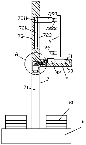
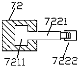
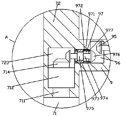
[0017] Such as Figure 1-Figure 4 As shown, a conveniently adjustable wedding lighting device of the present invention includes a cylinder 7 composed of an upper pillar 72 and a lower pillar 71 and a control platform 9 fixedly connected to the upper pillar 72. The bottom is provided with a movable chamber 723, the top of the lower pillar 71 is fixed with a rotating shaft 711, the top of the rotating shaft 711 passes through the bottom of the upper pillar 72 and extends into the movable chamber 723, and the top of the rotating shaft 711 is fixedly provided with a support Block 712, the top of the support block 712 is provided with a first toothed plate 714, the control table 9 is fixed on the upper pillar 72 outside the right side of the movable chamber 723, and the top of the control table 9 is provided with There is a second sliding groove 91, and a second sliding block 92 and a second screw rod 93 are arranged in the second sliding groove 91, and the second sliding block 92 ...


PUM


Abstract

The invention discloses a conveniently regulated and controlled wedding celebration lighting equipment which comprises a column body composed of an upper stand column and a lower stand column and a regulation and control table fixedly connected with the upper stand column. A movable cavity is formed in the bottom of the interior of the upper stand column, a rotating shaft is fixedly arranged at the top end of the lower stand column, the upper end of the rotating shaft penetrates the bottom of the upper stand column to extend into the movable cavity, a bearing block is fixedly arranged at the top end of the rotating shaft, and a first tooth-shaped disc is arranged at the top end of the bearing block; the regulation and control table is fixedly arranged at the position, outside the right side of the movable cavity, of the upper stand column, a second sliding groove is formed in the top end of the regulation and control table, and a second sliding block and a second screw rod are arranged in the second sliding groove and are in spiral line fit connection; and a first cavity is formed in the position, on the left side of the second sliding groove, in the regulation and control table, a second cavity is arranged between the bottom of the left side of the first cavity and the top end of the right side of the movable cavity, and the left side of the second screw rod penetrates the wall of the regulation and control table and extends into the first cavity to be in rotary fit connection.

Description

technical field [0001] The invention relates to the technical field of wedding lighting equipment, in particular to a conveniently adjustable wedding lighting equipment. Background technique [0002] In order to achieve better visual effects on the wedding stage, lighting equipment is often used. However, this lighting equipment needs to change its orientation and angle frequently to meet the lighting requirements of different directions. In the prior art, this lighting equipment is generally connected through activities. On the support rod, when it is necessary to adjust the direction and angle of the illumination, it is done manually. The operation process is cumbersome and laborious. At the same time, due to the instability of the manual operation, the lighting effect is poor and cannot meet the existing needs. . Contents of the invention [0003] The technical problem to be solved by the present invention is to provide a conveniently adjustable wedding lighting device...

Claims


Application Information

Patent Timeline
Patent Type & Authority Patents(China)
IPC IPC(8): F21S8/08F21V21/14F21V21/15
CPCF21S8/081F21V21/14F21V21/15
Inventor 吴玮佳
Owner 东莞市天翔航天科技有限公司
Why Eureka
Try Eureka