Integrated load limiting valve and actuator with mechanically adjustable output force

A kind of actuator and mechanical technology, applied in the field of servo loading system, can solve the problems of easy self-excited vibration, large size, inconvenient installation, etc., to solve the problem of interchangeability, not easy to self-excited vibration, accurate and reliable protection Effect

Active Publication Date: 2018-09-28
YANTAI ZHONGYU AEROHYDRAULIC
View PDF5 Cites 0 Cited by
  • Summary
  • Abstract
  • Description
  • Claims
  • Application Information

AI Technical Summary

Problems solved by technology

[0006] 1. Complex structure and high cost;
[0007] 2. Large size and inconvenient installation;
[0008] 3. Direct-acting pressure regulation, easy to self-excited vibration, difficult to adjust the load limit value, low control accuracy;
[0009] 4. The area ratio of the pressure regulating valve core at both ends of the valve corresponds to the area ratio of the two chambers of the actuator one by one, and there is no interchangeability and versatility
[0010] In view of the above deficiencies, this load limiting valve has not been widely accepted by the market
[0011] So far, although there is a great market demand for load limiting valves, there are no available products

Method used


Image

  • Integrated load limiting valve and actuator with mechanically adjustable output force
  • Integrated load limiting valve and actuator with mechanically adjustable output force

Examples


Embodiment 1

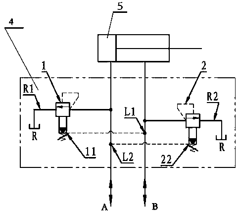
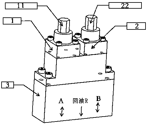
[0026] Example 1, such as figure 1 , a load limiting integrated valve 4, including a valve body 3, a first pilot relief valve 1 and a second pilot relief valve 2 are installed on the valve body, the oil discharge of the first pilot relief valve 1 The port L1 communicates with the oil inlet B of the second pilot relief valve, and the oil discharge port L2 of the second pilot relief valve communicates with the oil inlet A of the first pilot relief valve.

[0027] The load limiting integrated valve 4 of this embodiment can be directly installed on the actuator 5. During installation, the overflow port R1 of the first pilot relief valve and the relief port R2 of the second pilot relief valve are respectively The oil return port R of the valve body communicates with the total oil return circuit of the actuator, the oil inlet A of the first pilot relief valve 1 communicates with the first load chamber of the actuator, and the second pilot The oil inlet B of the type relief valve 2 ...

Embodiment 2

[0030] Embodiment 2, an actuator, including a first load chamber, a second load chamber, and a total oil return circuit, and the actuator also includes a first pilot relief valve 1 and a second pilot relief valve Valve 2, the drain port L1 of the first pilot relief valve 1 communicates with the oil inlet B of the second pilot relief valve, and the drain port L2 of the second pilot relief valve communicates with the first The oil inlet A of the pilot relief valve is connected to eliminate the influence of the change of load pressure on the control accuracy; the relief port R1 of the first pilot relief valve and the relief port of the second pilot relief valve R2 communicates with the main oil return circuit of the servo actuator through the oil return port R of the valve body, and the oil inlet A of the first pilot relief valve 1 communicates with the first load chamber of the actuator. The oil inlet B of the second pilot relief valve 2 communicates with the second load chamber...

Embodiment 3

[0033] The difference between Embodiment 3 and Embodiment 2 is that the shape and installation method of the valve body are different, and the oil inlet A of the first pilot relief valve 1 is connected with the first load of the actuator through the pipeline and the pipe joint. The chambers communicate, and the oil inlet B of the second pilot relief valve 2 communicates with the second load chamber of the actuator through pipelines and pipe joints.


PUM


Abstract

The invention provides a load limiting integrated valve and an actuator with mechanically adjustable output force. The load limiting integrated valve comprises a valve body and has the specialness that a first pilot overflow valve and a second pilot overflow valve are installed on the valve body; an oil drainage outlet of the first pilot overflow valve communicates with an oil inlet of the second pilot overflow valve; and an oil drainage outlet of the second pilot overflow valve communicates with an oil inlet of the first pilot overflow valve. Through the load limiting integrated valve, the influence of change of load pressure on the control precision is eliminated, the precision is high, and self-excited vibration is not liable to occur.

Description

technical field [0001] The patent of the invention relates to a mechanically adjustable load limiting integrated valve for controlling the output force of a servo actuator, which belongs to the technical field of servo loading systems. Background technique [0002] The servo loading system is used for static or fatigue tests of various test pieces. In most cases, the test piece is expensive and the test period is long. Abnormal damage to the test piece is not allowed during the test, otherwise it will cause great losses. This requires The loading system has a reliable protection function for the test piece. [0003] The servo loading system can generally set protection functions in the three links of hydraulic source, electrical control system and actuator-servo actuator, by cutting off the power source, changing the action and unloading of the servo actuator, etc. protection of. Among them, installing a protection module on the servo actuator is the best protection method...

Claims


Application Information

Patent Timeline
Patent Type & Authority Patents(China)
IPC IPC(8): F15B13/02
CPCF15B13/02F15B2013/002
Inventor 陈颖倪宇佩倪道卫张咸廷刘贵江腾祥龙李祥至
Owner YANTAI ZHONGYU AEROHYDRAULIC
Why Eureka
Try Eureka